
Videos
Verify whether the interconnection in the circuit in Figure P2.1 in the textbook is valid or not. Calculate the power developed by the current sources if the circuit is valid. Explain the reason if the interconnection in the circuit is not valid.
Answer to Problem 1P
The interconnection in the given circuit is valid and the power developed by the current sources is 1700 W.
Explanation of Solution
Given data:
Refer to Figure P2.1 in the textbook for required data.
Formula used:
Write the expression for power developed by the source (voltage or current) as follows:
Here,
Calculation:
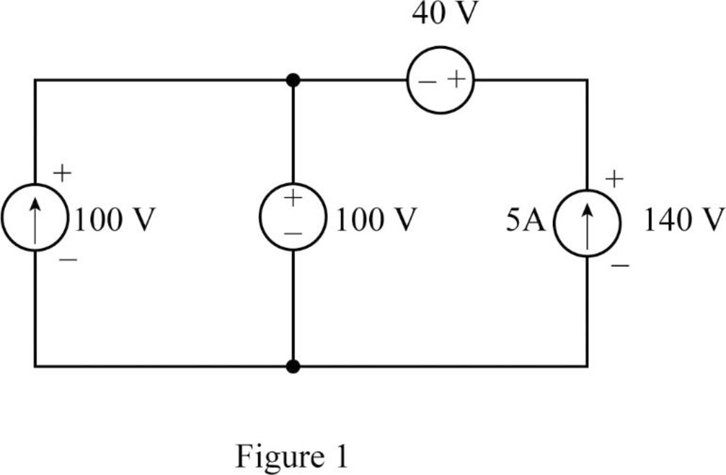
From the given circuit, it is clear that, the voltage drop across the 10 A current source is 100 V and the voltage drop from the negative terminal of the 40 V voltage source to the bottom terminal of the 5 A current source must be 100 V.
In order to maintain the voltage drop of 100 V from the negative terminal of the 40 V voltage source to the bottom terminal of the 5 A current source the voltage drop across 5 A current source must be 140 V.
From the analysis, redraw the circuit as shown in Figure 1.
All the sources in the given circuit are independent sources. The independent voltage source can carry any current that required by the connection and the independent current source can support any voltage that required by the connection.
From the analysis, the voltage drop across the sources is satisfied. Therefore, the interconnection in the given circuit is valid.
Rewrite the expression in Equation (1) to find the power developed by the 10 A current source as follows:
From Figure 1, current 10 A enters from the negative terminal of 100 V. Therefore, the values of
The negative sign indicates the delivered power by the source. Therefore, the power developed by the 10 A current source is 1000 W.
Rewrite the expression in Equation (1) to find the power developed by the 5 A current source as follows:
From Figure 1, current 5 A enters from the negative terminal of 140 V. Therefore, the values of
As the negative sign indicates the delivered power by the source, the power developed by the 5 A current source 700 W.
Write the expression for power developed by the both current sources as follows:
Substitute 1000 W for
Conclusion:
Thus, the interconnection in the given circuit is valid and the power developed by the current sources is 1700 W.
Want to see more full solutions like this?
Chapter 2 Solutions
Electric Circuits. (11th Edition)


 Introductory Circuit Analysis (13th Edition)Electrical EngineeringISBN:9780133923605Author:Robert L. BoylestadPublisher:PEARSON
 Delmar's Standard Textbook Of ElectricityElectrical EngineeringISBN:9781337900348Author:Stephen L. HermanPublisher:Cengage Learning
 Programmable Logic ControllersElectrical EngineeringISBN:9780073373843Author:Frank D. PetruzellaPublisher:McGraw-Hill Education
 Fundamentals of Electric CircuitsElectrical EngineeringISBN:9780078028229Author:Charles K Alexander, Matthew SadikuPublisher:McGraw-Hill Education
 Electric Circuits. (11th Edition)Electrical EngineeringISBN:9780134746968Author:James W. Nilsson, Susan RiedelPublisher:PEARSON
 Engineering ElectromagneticsElectrical EngineeringISBN:9780078028151Author:Hayt, William H. (william Hart), Jr, BUCK, John A.Publisher:Mcgraw-hill Education,