
Principles And Applications Of Electrical Engineering
6th Edition
ISBN: 9789814577410
Author: RIZZONI
Publisher: Mcgraw-Hill
expand_more
expand_more
format_list_bulleted
Concept explainers
Videos
Textbook Question
Chapter 2, Problem 2.10HP
The charge cycle shown in Figure P2.10 is anexample of a two-rate charge. The current is heldconstant at 70 mA for 1 h. Then it is switched to 60 mA for the next 1 h. Find:
a. The total charge transferred to the battery.
b. The total energy transferred to the battery.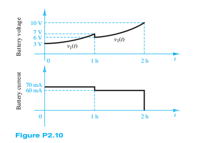
Expert Solution & Answer
Want to see the full answer?
Check out a sample textbook solution
Students have asked these similar questions
sketch vL1 and vR2 on a graph. mark the labels in microseconds one time constant after the charging phase begins and the value of each voltage at that time
Q6. How potential energy of water is converted into Electrical Energy?
Q7. Draw the V-I Characteristic of Solar PV Cell ?
A- Calculate the equivalent resistances (???) of the following circuits. (The resistance value of the diodes in the conduction will be taken as 0, the resistance values of the diodes in the insulation will be taken as infinity. R1=10 ohms)
B- Explain P and N type items by drawing figures. Explain the element formed by the non-polar combination of these substances by drawing a figure.
Chapter 2 Solutions
Principles And Applications Of Electrical Engineering
Ch. 2 - A free electron has an initial potential energy...Ch. 2 - The units for voltage, current, and resistance are...Ch. 2 - A particular fully charged battery can deliver...Ch. 2 - The charge cycle shown in Figure P2.4 is an...Ch. 2 - Batteries (e.g., lead-acid batteries) store...Ch. 2 - What determines: a. The current through an ideal...Ch. 2 - An automotive battery is rated at 120 A-h. This...Ch. 2 - A car battery kept in storage in the basement...Ch. 2 - Suppose the current through a wire is given by the...Ch. 2 - The charge cycle shown in Figure P2.10 is...
Ch. 2 - The charging scheme used in Figure P2.11 is...Ch. 2 - The charging scheme used in Figure P2.12 is...Ch. 2 - Use KCL to determine the unknown currents in the...Ch. 2 - Use KCL to find the current i1 and i2 in Figure...Ch. 2 - Use KCL to find the current i1,i2, and i3 in the...Ch. 2 - Use KVL to find the voltages v1,v2, and v3 in...Ch. 2 - Use KCL to determine the current i1,i2,i3, and i4...Ch. 2 - In the circuits of Figure P2.18, the directions...Ch. 2 - Find the power delivered by each source in Figure...Ch. 2 - Determine whether each element in Figure P2.20 is...Ch. 2 - In the circuit of Figure P2.21, determine the...Ch. 2 - For the circuit shown in Figure P2.22: a....Ch. 2 - For the circuit shown in Figure P2.23,...Ch. 2 - For the circuit shown in Figure P2.24, determine...Ch. 2 - For the circuit shown in Figure P2.25, determine...Ch. 2 - Prob. 2.26HPCh. 2 - Prob. 2.27HPCh. 2 - Prob. 2.28HPCh. 2 - Prob. 2.29HPCh. 2 - Prob. 2.30HPCh. 2 - Prob. 2.31HPCh. 2 - In the circuit of Figure P2.32, assume v2=vs/6 and...Ch. 2 - Prob. 2.33HPCh. 2 - An incandescent light bulb rated at 100 W will...Ch. 2 - An incandescent lightbulb rated at 60 W...Ch. 2 - Refer to Figure P2.36, and assume that...Ch. 2 - Refer to Figure P2.37, and assume that...Ch. 2 - Refer to Figure P2.38, and assume...Ch. 2 - Prob. 2.39HPCh. 2 - With no load attached, the voltage at the...Ch. 2 - Prob. 2.41HPCh. 2 - For the circuits of Figure P2.42, determine the...Ch. 2 - At an engineering site, a 1-hp motor is placed...Ch. 2 - Cheap resistors are fabricated by depositing a...Ch. 2 - Prob. 2.45HPCh. 2 - Use KCL and Ohm’s law to determine the current...Ch. 2 - Refer to Figure P2.13. Assume R0=1,R1=2,R2=3,R3=4...Ch. 2 - Apply KCL and Ohm’s law to find the power supplied...Ch. 2 - Refer to Figure P2.49 and assume...Ch. 2 - Refer to Figure P2.49 and assume...Ch. 2 - Prob. 2.51HPCh. 2 - The voltage divider network of Figure P2.52 is...Ch. 2 - Find the equivalent resistance seen by the source...Ch. 2 - Find the equivalent resistance seen by the source...Ch. 2 - In the circuit of Figure P2.55, the power absorbed...Ch. 2 - Find the equivalent resistance between terminals...Ch. 2 - For the circuit shown in Figure P2.57, find the...Ch. 2 - For the circuit shown in Figure P2.58,find the...Ch. 2 - Refer to Figure P2.59. Assume...Ch. 2 - Find the equivalent resistance seen by the source...Ch. 2 - For the circuit shown in Figure P2.61. assume...Ch. 2 - Determine the equivalent resistance of the...Ch. 2 - For the circuit shown in Figure P2.58, assume...Ch. 2 - In the circuit of Figure P2.64, find the...Ch. 2 - Refer to Figure P2.64 and determine the equivalent...Ch. 2 - Find the equivalent resistance seen by the source...Ch. 2 - Determine the voltage vo between nodes A and Bin...Ch. 2 - Refer to Figure P2.68 and assume...Ch. 2 - Prob. 2.69HPCh. 2 - Prob. 2.70HPCh. 2 - Prob. 2.71HPCh. 2 - The circuit of Figure P2.72 is used to measure the...Ch. 2 - Consider the practical ammeter, depicted in Figure...Ch. 2 - Prob. 2.74HPCh. 2 - Prob. 2.75HPCh. 2 - Prob. 2.76HPCh. 2 - A voltmeter is used to determine the voltage...Ch. 2 - Prob. 2.78HPCh. 2 - Figure P2.79 shows an aluminum cantilevered beam...Ch. 2 - Refer to Figure P2.79 but assume that the...
Knowledge Booster


Learn more about
Need a deep-dive on the concept behind this application? Look no further. Learn more about this topic, electrical-engineering and related others by exploring similar questions and additional content below.Similar questions
- Considering that the power loss of a resistor is RI^2 and the information in the manual’s background section, derive an expression for the energy lost through Joule heating in a resistor when a capacitor completely discharges.arrow_forwardQuestion 3 a) The Fermi level of a solid-state body is the thermodynamic work required to add one electron to the body. The Fermi level does not include the work required to remove the electron from wherever it came from. With the aid of diagram discuss the importance of the Fermi Energy level, especially its relevance to electron flow in a pn-junction diode. b) Discuss the I/V characteristics curve of a practical Germanium diode and explain in detail how the forward and reverse are achieved. Support your explanation with a suitable circuit diagram with a voltage source and RC components connected across the p-n junctionarrow_forwardA. Explain the difference between charging current andfaradaic current. B. What is the purpose of waiting 1s after a voltage pulse before measuring current in sampled current voltammetry? C. Why is square wave voltammetry more sensitive than sampled current voltammetry?arrow_forward
- the current (in mA) in each resistor shown in the figure aboveIR1IR2IR3 the potential difference between points c and f (Give the magnitude of your answer in volts and select the point of highest potential.) magnitude of potential difference What If? If all of the resistors in the circuit were decreased in value by a factor of 1,000, would the current in each resistor simply increase by a factor of 1,000? Explain your answer.arrow_forwardAnswer the following questions according to the above. Remember Kirchhoff's laws when making your calculations in this question. a) According to the given graph, how many volts is the voltage value on it when this Zener diode is on a flat supply? b) According to the given graph, how many volts is the voltage value on this Zener Diode when it is on reverse supply? c) Calculate how many values V?−?? are when the zener current is 0 mA. D) Calculate how much the value of ??−?? is when the zener current is at its maximum value.arrow_forwardQ2: For the single phase full wave semi controlled rectifier shown: 1-Draw the v-i waveforms for the circuit vm 2-Prove that: lav =~ (1+cos @) 3-Maximum voltage across the load if the AC supply voltage is 208V .arrow_forward
- "What is the initial resistance of a material in ohm, given: 23 ohms as the final resistance, 250C and 480C as the initial and final temperature and 0.00456/0C as the temperature coefficient of resistance of the material at 480C?"arrow_forwardSince R1=4.51 Kohm, R2=1.19 Kohm R3=2.74Kohm R4=5.60Kohm VCC=23.00V and diode silicon in the circuit given in the figure, find the current passing through the diode in mAarrow_forward3. It is required to design a full-wave rectifier circuit using the circuit shown below to provide an average output vol tage of10 V. find the required turns ratio of the transformer. Assume that a conducting diode has a voltage drop of0.7 V. The ac line vol tage is120 Vrms.arrow_forward
- In the circuit, diode D1 has n = 1.4 and has an operating point I D = 1mA at V D =0.7 V and is at room temperature. Diode D2 has an area that is 20 times larger than D1 but isotherwise the same. a) What is the current through diode D1?b) What is the value of the saturation current, Is for diode D2?c) What is the voltage Vx ? d) Determine the value of R to make Vo = -0.2Varrow_forwardA semiconductor substrate of 1 mm2 cross section is used to design a resistor. The doped-p concentration is 5'10^16 at/cm^3. and μp=500cm^2/Vxs We ask:(a) Calculate the electrical resistance for dimensions a= 100 mm, l= 500 mm, e= 0.1 mm.(b) The current density circulating for a voltage of 5 V.(c) The dopant concentration for R= 100 W.arrow_forwardConsider the battery charging circuit shown in Figure 9.25 on page 476. The ac source has a peak value of 24 V and a frequency of 60 Hz. The resistance is 2 Ω, the diode is ideal, and VB = 12 V. Determine the average current (i.e., the value of the charge that passes through the battery in 1 second). Suppose that the battery starts from a totally discharged state and has a capacity of 100 ampere hours. How long does it take to fully charge the battery?arrow_forward
arrow_back_ios
SEE MORE QUESTIONS
arrow_forward_ios
Recommended textbooks for you
 Introductory Circuit Analysis (13th Edition)Electrical EngineeringISBN:9780133923605Author:Robert L. BoylestadPublisher:PEARSON
 Delmar's Standard Textbook Of ElectricityElectrical EngineeringISBN:9781337900348Author:Stephen L. HermanPublisher:Cengage Learning
 Programmable Logic ControllersElectrical EngineeringISBN:9780073373843Author:Frank D. PetruzellaPublisher:McGraw-Hill Education
 Fundamentals of Electric CircuitsElectrical EngineeringISBN:9780078028229Author:Charles K Alexander, Matthew SadikuPublisher:McGraw-Hill Education
 Electric Circuits. (11th Edition)Electrical EngineeringISBN:9780134746968Author:James W. Nilsson, Susan RiedelPublisher:PEARSON
 Engineering ElectromagneticsElectrical EngineeringISBN:9780078028151Author:Hayt, William H. (william Hart), Jr, BUCK, John A.Publisher:Mcgraw-hill Education,
Introductory Circuit Analysis (13th Edition)
Electrical Engineering
ISBN:9780133923605
Author:Robert L. Boylestad
Publisher:PEARSON
Delmar's Standard Textbook Of Electricity
Electrical Engineering
ISBN:9781337900348
Author:Stephen L. Herman
Publisher:Cengage Learning
Programmable Logic Controllers
Electrical Engineering
ISBN:9780073373843
Author:Frank D. Petruzella
Publisher:McGraw-Hill Education
Fundamentals of Electric Circuits
Electrical Engineering
ISBN:9780078028229
Author:Charles K Alexander, Matthew Sadiku
Publisher:McGraw-Hill Education
Electric Circuits. (11th Edition)
Electrical Engineering
ISBN:9780134746968
Author:James W. Nilsson, Susan Riedel
Publisher:PEARSON
Engineering Electromagnetics
Electrical Engineering
ISBN:9780078028151
Author:Hayt, William H. (william Hart), Jr, BUCK, John A.
Publisher:Mcgraw-hill Education,
How does an Alternator Work ?; Author: Lesics;https://www.youtube.com/watch?v=tiKH48EMgKE;License: Standard Youtube License