
Electrical Engineering: Principles & Applications (7th Edition)
7th Edition
ISBN: 9780134484143
Author: Allan R. Hambley
Publisher: PEARSON
expand_more
expand_more
format_list_bulleted
Concept explainers
Videos
Textbook Question
Chapter 2, Problem 2.1PT
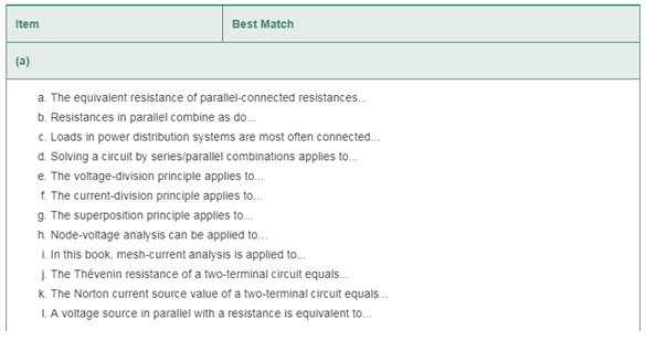
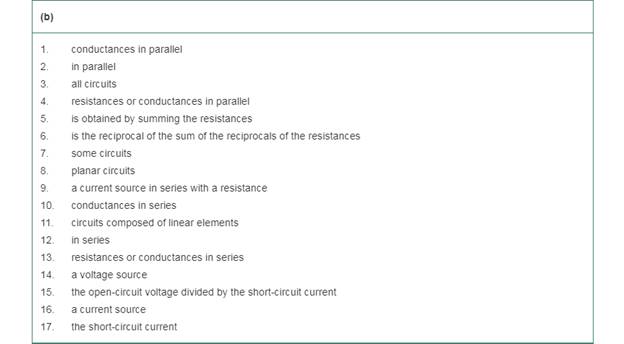
Match each entry in Table T2.1(a) with the best choice from the list given in Table T2.1(b) for circuits composed of sources and resistances [Items in Table T2.1(b) may be used more than once or not at all.]Table T2.1
Expert Solution & Answer
Want to see the full answer?
Check out a sample textbook solution
Students have asked these similar questions
In solving a network, what rule must you observe when writing KCL equations? Why?
Find the equivalent resistance for the infinite network shown in Figure P2.12(a). Because of its form, this network is called a semi-infinite ladder. [Hint: If another section is added to the ladder as shown in Figure P2.12(b), the equivalent resistance is the same. Thus, working from Figure P2.12(b), we can write an expression for Req in terms of Req.Then, we can solve for Req.
For the circuit shown in Figure P2.35, determinethe power absorbed by the variable resistor R, rangingfrom 0 to 20 . Plot the power absorption as afunction of R.
Chapter 2 Solutions
Electrical Engineering: Principles & Applications (7th Edition)
Ch. 2 - Reduce each of the networks shown in Figure P2.1...Ch. 2 - A 4- resistance is in series with the parallel...Ch. 2 - Find the equivalent resistance looking into...Ch. 2 - Suppose that we need a resistance of 1.5 k and...Ch. 2 - Find the equivalent resistance between terminals a...Ch. 2 - Find the equivalent resistance between terminals a...Ch. 2 - What resistance in parallel with 120 results in...Ch. 2 - Determine the resistance between terminals a and b...Ch. 2 - Two resistances having values of R and 2R are in...Ch. 2 - A network connected between terminals a and b...
Ch. 2 - Two resistances R1 and R2 are connected in...Ch. 2 - Find the equivalent resistance for the infinite...Ch. 2 - If we connect n 1000- resistances in parallel,...Ch. 2 - The heating element of an electric cook top has...Ch. 2 - We are designing an electric space heater to...Ch. 2 - Sometimes, we can use symmetry considerations to...Ch. 2 - The equivalent resistance between terminals a and...Ch. 2 - Three conductances G1 G2, and G3 are in series....Ch. 2 - Most sources of electrical power behave as...Ch. 2 - The resistance for the network shown in Figure...Ch. 2 - Often, we encounter delta-connected loads such as...Ch. 2 - What are the steps in solving a circuit by network...Ch. 2 - Find the values of i1 and i2 in Figure P2.23....Ch. 2 - Find the voltages v1 and v2 for the circuit shown...Ch. 2 - Find the values of v and i in Figure P2.25. Figure...Ch. 2 - Consider the circuit shown in Figure P2.24....Ch. 2 - Find the voltage v and the currents i1 and 12 for...Ch. 2 - Find the values of vs, v1, and i2 in Figure P2.28....Ch. 2 - Find the values of i1 and i2 in Figure P2.29....Ch. 2 - Consider the cirrcuit shown in Figure P2.30 Find...Ch. 2 - Solve for the values of i1, i2, and the powers for...Ch. 2 - The 12-V source in Figure P2.32 is delivering 36...Ch. 2 - Refer to the circuit shown in Figure P2.33. With...Ch. 2 - Find the values of i1 and i2 in Figure P2.34. Find...Ch. 2 - Find the values of i1 and i2 in Figure P2.35...Ch. 2 - Use the voltage-division principle to calculate...Ch. 2 - Use the current-division principle to calculate i1...Ch. 2 - Use the voltage-division principle to calculate...Ch. 2 - Use the current-division principle to calculate...Ch. 2 - Suppose we need to design a voltage-divider...Ch. 2 - A source supplies 120 V to the series combination...Ch. 2 - We have a 60- resistance, a 20- resistance, and...Ch. 2 - A worker is standing on a wet concrete floor,...Ch. 2 - Suppose we have a load that absorbs power and...Ch. 2 - We have a load resistance of 50 that we wish to...Ch. 2 - We have a load resistance of 1 k that we wish to...Ch. 2 - The circuit of Figure P2.47 is similar to networks...Ch. 2 - Write equations and solve for the node voltages...Ch. 2 - Solve for the node voltages shown in Figure P2.49....Ch. 2 - Solve for the node voltages shown in Figure P2.50....Ch. 2 - Given R1=4 , R2=5 , R2=8 , R4=10 , R5=2 , and...Ch. 2 - Determine the value of i1 in Figure P2.52 using...Ch. 2 - Given R1=15 , R5=5 , R3=20 , R4=10 , R5=8 , R6=4 ,...Ch. 2 - In solving a network, what rule must you observe...Ch. 2 - Use the symbolic features of MATLAB to find an...Ch. 2 - Solve for the values of the node voltages shown in...Ch. 2 - Solve for the node voltages shown in Figure P2.57....Ch. 2 - Solve for the power delivered to the 8- ...Ch. 2 - Solve for the node voltages shown in Figure P2.59....Ch. 2 - Find the equivalent resistance looking into...Ch. 2 - Find the equivalent resistance looking into...Ch. 2 - Figure P2.62 shows an unusual voltage-divider...Ch. 2 - Solve for the node voltages in the circuit of...Ch. 2 - We have a cube with 1- resistances along each...Ch. 2 - Solve for the power delivered to the 15- resistor...Ch. 2 - Determine the value of v2 and the power delivered...Ch. 2 - Use mesh-current analysis to find the value of i1...Ch. 2 - Solve for the power delivered by the voltage...Ch. 2 - Use mesh-current analysis to find the value of v...Ch. 2 - Use mesh-current analysis to find the value of i3...Ch. 2 - Use mesh-current analysis to find the values of i1...Ch. 2 - Find the power delivered by the source and the...Ch. 2 - Use mesh-current analysis to find the values of i1...Ch. 2 - Use mesh-current analysis to find the values of i1...Ch. 2 - The circuit shown in Figure P2.75 is the dc...Ch. 2 - Use MATLAB and mesh-current analysis to determine...Ch. 2 - Connect a 1-V voltage source across terminals a...Ch. 2 - Connect a 1-V voltage source across the terminals...Ch. 2 - Use MATLAB to solve for the mesh currents in...Ch. 2 - Find the Thévenin and Norton equivalent circuits...Ch. 2 - We can model a certain battery as a voltage source...Ch. 2 - Find the Thévenin and Norton equivalent circuits...Ch. 2 - Find the Thévenin and Norton equivalent circuits...Ch. 2 - Find the Thévenin arid Norton equivalent circuits...Ch. 2 - An automotive battery has an open-circuit voltage...Ch. 2 - A certain two-terminal circuit has an open-circuit...Ch. 2 - If we measure the voltage at the terminals of a...Ch. 2 - Find the Thévenin and Norton equivalent circuits...Ch. 2 - Find the maximum power that can be delivered to a...Ch. 2 - Find the maximum power that can be delivered to a...Ch. 2 - Figure P2.91 shows a resistive load RL connected...Ch. 2 - Starling from the Norton equivalent circuit with a...Ch. 2 - A battery can be modeled by a voltage source Vt in...Ch. 2 - Use superposition to find the current i in Figure...Ch. 2 - Solve for is in Figure P2.49 by using...Ch. 2 - Solve the circuit shown in Figure P2.48 by using...Ch. 2 - Solve for i1 in Figure P2.34 by using...Ch. 2 - Another method of solving the circuit of Figure...Ch. 2 - Use the method of Problem P2.98 for the circuit of...Ch. 2 - Solve for the actual value of i6 for the circuit...Ch. 2 - Device A shown in Figure P2.101 has v=3i2 for i 0...Ch. 2 - The Wheatstone bridge shown in Figure 2.66 is...Ch. 2 - The Wheatstone bridge shown in Figure 2.66has...Ch. 2 - In theory, any values can be used for R1 and R3 in...Ch. 2 - Derive expressions for the Thévenin voltage and...Ch. 2 - Derive Equation 2.93 for the bridge circuit of...Ch. 2 - Prob. 2.107PCh. 2 - Explain what would happen if, in wiring the bridge...Ch. 2 - Match each entry in Table T2.1(a) with the best...Ch. 2 - Consider the circuit of Figure T2.2 with vs=96V ,...Ch. 2 - Write MATLAB code to solve for the node voltages...Ch. 2 - Write a set of equations that can be used to solve...Ch. 2 - Determine the Thévenin and Norton equivalent...Ch. 2 - According to the superposition principle, what...Ch. 2 - Determine the equivalent resistance between...Ch. 2 - Transform the 2-A current source and 6- ...
Knowledge Booster


Learn more about
Need a deep-dive on the concept behind this application? Look no further. Learn more about this topic, electrical-engineering and related others by exploring similar questions and additional content below.Similar questions
- 3. Given: VS1: 18 voltsVS2: -1 voltsRB1: 1000 ohmsRB2: 6500 ohmsRB3: 8000 ohmsRB4: 5000 ohmsB=beta: 75RE: 540 ohmsVE: ? voltsarrow_forwardthe current (in mA) in each resistor shown in the figure aboveIR1IR2IR3 the potential difference between points c and f (Give the magnitude of your answer in volts and select the point of highest potential.) magnitude of potential difference What If? If all of the resistors in the circuit were decreased in value by a factor of 1,000, would the current in each resistor simply increase by a factor of 1,000? Explain your answer.arrow_forwardUsing the diagram below and the component photos from page 4, draw the realistic experimental setup you will use in this lab. Draw the actual apparatus with wires and other electrical elements, connected as they will be on your lab table. Be sure to label components, junctions, and distances as appropriate.arrow_forward
- A resistor of resistance ? is supplied by a battery which consists of voltage source ? in series with an internal resistance ?. Plot the power ? as a function of the resistance ? for 1 Ω < ? < 10 Ω given that ? = 12 V and ? = 4 Ω. From the resulting plot, when does the maximum power transfer occur and what is this maximum power being dissipated by the load?arrow_forwardHow does the power, P, dissipated by a resistor depend on the indicated parameter (resistance, R,of the resistor, or the voltage or current of the supply) for each of the following scenarios? I amlooking for a mathematical equation for power as a function of the indicated parameter followed bya description of the dependence - does the power increase, decrease, remain the same or some otherdependence, as the parameter is increased? (and if other, describe.) If it is increasing or decreasing,by what factor does the power change if the parameter is increased by a factor of 3?(a) Constant R, powered by ideal voltage supply (We will examine real batteries that have internalresistance in class and the next homework.) How does P depend on the voltage, V, of thesupply?(b) Constant R, powered by ideal current supply. How does power depend on the current I?(c) Ideal battery operating at a fixed voltage, powering a variable resistor R. How does P dependon the resistance, R, of the resistor?(d)…arrow_forwardMore five examples regarding this KCL method(with circuit figures and complete solution)arrow_forward
- A metallic wire is stretched from original length of 2 m to 5 m. If the original cross-sectional area is 4 square millimeters and original resistance is 8 ohms, determine the new resistance (in ohms) of the metallic wire. Assume the volume of the wire is preserved.arrow_forwardV2b please help me with the full solution and answer thank youarrow_forwardThe resistance for the network shown in Figure P2.20 between terminals a and b with copen circuited is Rab=50 Ω. Similarly, the resistance between terminals b and c with a open is Rbc=100 Ω,and between c and a with b open is Rca=70 Ω. Now, suppose that a short circuit isconnected from terminal b to terminal c, and determine the resistance between terminal a andthe shorted terminals b–c.arrow_forward
- a) Mention few factors how variation of resistance is possible in practice. Compute the resistance of a 10m carbon wire with cross section area of 100 mm² (note: Carbon resistivity (p) is 3.5 x 10⁻⁵ohm-m, and R= pL/A). b).What do we call the special cases when resistance is 0 ohm, and when resistance is infinite?arrow_forwardGiven the circuit, where the rate at which R1 is dissipating electrical energy is 20.0W. When the total current flowing in the circuit is 3.50A, find:a.) R1 and R2b.) Emf of the batteryc.) Current through both R2 and the 10.0-ohm resistance d.) What is the total electrical consumptionarrow_forwardCurrent is the flow of charges in a directed path. When we connect yourmobile phone charger to the sockets in your various homes, charges startflowing through. Describe into details where these charges are generatedfrom and the processes involved.arrow_forward
arrow_back_ios
SEE MORE QUESTIONS
arrow_forward_ios
Recommended textbooks for you
 Introductory Circuit Analysis (13th Edition)Electrical EngineeringISBN:9780133923605Author:Robert L. BoylestadPublisher:PEARSON
 Delmar's Standard Textbook Of ElectricityElectrical EngineeringISBN:9781337900348Author:Stephen L. HermanPublisher:Cengage Learning
 Programmable Logic ControllersElectrical EngineeringISBN:9780073373843Author:Frank D. PetruzellaPublisher:McGraw-Hill Education
 Fundamentals of Electric CircuitsElectrical EngineeringISBN:9780078028229Author:Charles K Alexander, Matthew SadikuPublisher:McGraw-Hill Education
 Electric Circuits. (11th Edition)Electrical EngineeringISBN:9780134746968Author:James W. Nilsson, Susan RiedelPublisher:PEARSON
 Engineering ElectromagneticsElectrical EngineeringISBN:9780078028151Author:Hayt, William H. (william Hart), Jr, BUCK, John A.Publisher:Mcgraw-hill Education,
Introductory Circuit Analysis (13th Edition)
Electrical Engineering
ISBN:9780133923605
Author:Robert L. Boylestad
Publisher:PEARSON
Delmar's Standard Textbook Of Electricity
Electrical Engineering
ISBN:9781337900348
Author:Stephen L. Herman
Publisher:Cengage Learning
Programmable Logic Controllers
Electrical Engineering
ISBN:9780073373843
Author:Frank D. Petruzella
Publisher:McGraw-Hill Education
Fundamentals of Electric Circuits
Electrical Engineering
ISBN:9780078028229
Author:Charles K Alexander, Matthew Sadiku
Publisher:McGraw-Hill Education
Electric Circuits. (11th Edition)
Electrical Engineering
ISBN:9780134746968
Author:James W. Nilsson, Susan Riedel
Publisher:PEARSON
Engineering Electromagnetics
Electrical Engineering
ISBN:9780078028151
Author:Hayt, William H. (william Hart), Jr, BUCK, John A.
Publisher:Mcgraw-hill Education,
How do Solar cells work?; Author: Lesics;https://www.youtube.com/watch?v=L_q6LRgKpTw;License: Standard Youtube License