
Electric machinery fundamentals
5th Edition
ISBN: 9780073529547
Author: Chapman, Stephen J.
Publisher: MCGRAW-HILL HIGHER EDUCATION
expand_more
expand_more
format_list_bulleted
Concept explainers
Videos
Textbook Question
Chapter 2, Problem 2.24P
Figure P2-4 shows a one-line diagram of a power system consisting of a three-phase, 480-V, 60-Hz generator supplying two loads through a transmission line with a pair of transformers at either end. (NOTE: One-line diagrams are described in Appendix A, the discussion of three-phase power circuits.)
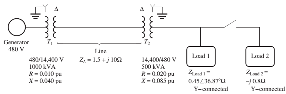
FIGURE P2-4
A one-line diagram of the power system of Problem 2-24. Note that some impedance values are given in the per-unit system, while others are given in ohms.
- Sketch the per-phase equivalent circuit of this power system.
- With the switch opened, find the real power P, reactive power Q, and apparent power S supplied by the generator. What is the power factor of the generator?
- With the switch closed, find the real power P, reactive power Q, and apparent power S supplied by the generator. What is the power factor of the generator?
- What are the transmission losses (transformer plus transmission line losses) in this system with the switch open? With the switch closed? What is the effect of adding Load 2 to the system?
Expert Solution & Answer
Want to see the full answer?
Check out a sample textbook solution
Students have asked these similar questions
List and describe three (3) losses that occur in power transformers.
a) For the 2-Bus AC system given in Figure (a) find V1 (amplitude and angle). All the values are given in p.u. Note: Mind complex power concept!
b) For the HVDC equivalent circuit given in Figure (b) calculate V2. All the values are given in p.u.
Now that a 1:15 step-up transformer is installed at the output of the generator and a 15: 1transformer is installed at the end of the transmission line, as depicted in Figure Q3(b).
(i)Determine the new load voltage/generated voltage ratioand power loss in the transmission line.
(ii)By assuming the transformer is ideal, evaluate your answers with those obtained in 3(a)
Chapter 2 Solutions
Electric machinery fundamentals
Ch. 2 - Is the turns ratio of a transformer the same as...Ch. 2 - Why does the magnetization current impose an upper...Ch. 2 - What components compose the excitation current of...Ch. 2 - What is the leakage flux in a transformer? Why is...Ch. 2 - List and describe the types of losses that occur...Ch. 2 - Why does the power factor of a load affect the...Ch. 2 - Why does the short-circuit test essentially show...Ch. 2 - Why does the open-circuit test essentially show...Ch. 2 - How does the per-unit system of measurement...Ch. 2 - Why can autotransformers handle more power than...
Ch. 2 - What are transformer taps? Why are they used?Ch. 2 - What are the problems associated with the Y—Y...Ch. 2 - What is a TCUL transformer?Ch. 2 - How can three-phase transformation be accomplished...Ch. 2 - Prob. 2.15QCh. 2 - Can a 60-Hz transformer be operated on a 50-Hz...Ch. 2 - What happens to a transformer when it is first...Ch. 2 - What is a potential transform? How is it used?Ch. 2 - What is a current transformer? How is it used?Ch. 2 - A distribution transformer is rated at 18 kVA,...Ch. 2 - Why does one hear a hum when standing near a large...Ch. 2 - A 100-kVA, 8000/277-V distribution transformer has...Ch. 2 - A single-phase power system is shown in Figure...Ch. 2 - Consider a simple power system consisting of an...Ch. 2 - The secondary winding of a real transformer has a...Ch. 2 - When travelers from the USA and Canada visit...Ch. 2 - A 1000-VA, 230/115-V transformer has been tested...Ch. 2 - A 30-kVA, 8000/230-V distribution transformer has...Ch. 2 - A 150-MVA, 15/200-kV, single-phase power...Ch. 2 - A 5000-kVA, 230/13.8-kV, single-phase power...Ch. 2 - A three-phase transformer bank is to handle 500...Ch. 2 - A 100-MVA, 230/115-kV, Y three-phase power...Ch. 2 - Three 20-kVA, 24,000/277-V distribution...Ch. 2 - A 14,000/480-V, three-phase, Y-connected...Ch. 2 - A 13.8-kV, single-phase generator supplies power...Ch. 2 - An autotransformer is used to connect a 12.6-kV...Ch. 2 - Prove the following statement: If a transformer...Ch. 2 - A 10-kVA, 480/120-V conventional transformer is to...Ch. 2 - A 10-kVA, 480/120-V conventional transformer is to...Ch. 2 - Two phases of a 14.4-kV, three-phase distribution...Ch. 2 - A 50-kVA, 20,000/480-V, 60-Hz, single-phase...Ch. 2 - Prove that the three-phase system of voltages on...Ch. 2 - Prove that the three-phase system of voltages on...Ch. 2 - A single-phase, 10-kVA, 480/120-V transformer is...Ch. 2 - Figure P2-4 shows a one-line diagram of a power...
Knowledge Booster


Learn more about
Need a deep-dive on the concept behind this application? Look no further. Learn more about this topic, electrical-engineering and related others by exploring similar questions and additional content below.Similar questions
- Consider two interconnected voltage sources connected by a line of impedance Z=jX, as shown in Figure 2.27. (a) Obtain expressions for P12 and Q12. (b) Determine the maximum power transfer and the condition for it toarrow_forwardSubject: Electrical ApparatusA typical single-phase transformer has a certain value of voltage regulation when connected to the load. If the voltage regulation is equal to zero, what is the behavior of the load connected to the transformer?arrow_forwardIn the circuit in Figure 2, the capacitor connected to the a-b terminals of the transformer anda circuit consisting of resistance is defined as a load circuit. a)Find the average power spent by the load circuit? b) How much of the average power calculated in a) by the resistance in the load circuit and how muchspent by the capacitor? Comment on the results obtained?arrow_forward
- How do I solve this using Kirchoff's Voltage Law?arrow_forwardplease write introduction about AC Circuits – Series and Parallel connected Circuitsarrow_forwardYou have been given two single-phase transformers to determine their characteristics. Using the laboratory equipment and transformers provided, produce a laboratory report which includes details of the transformers: Equivalent circuit Regulation Efficiency From the report, suggests a typical application for each transformer with justifications for suggested operational requirements.arrow_forward
- Find the number of turns n1 and n2 in a single phase transformer (open circuit )explaining the procedure and equations done ,utilising the block parameters of The linear transformer below ,which should be sufficient to do so .arrow_forwardDiscuss the role of transformers in power systems and the various types of transformers used.arrow_forwardSketch and label the main working components of a wind turbine. Describe the functionality of each of the parts. List various foundation structure for offshore wind turbines and describe their advantages and disadvantages and relate their configuration to appropriate water depth.arrow_forward
- Explain the concept of load shedding in the context of power systems.arrow_forwardA 1000-VA 380 / 110 V conventional transformer is to be used to supply power from a 490-V source to a110-V load. Consider the transformer to be ideal, and assume that all insulation can handle 490 V. (a) Sketch the transformer connection that will do the required job (b) Find the kVA rating of the transformer in the configuration. (c) Find the maximum primary and secondary currents under these conditionsarrow_forwardCombination circuit what is PT? RT? IT? Voltage Across each load?arrow_forward
arrow_back_ios
SEE MORE QUESTIONS
arrow_forward_ios
Recommended textbooks for you
 Power System Analysis and Design (MindTap Course ...Electrical EngineeringISBN:9781305632134Author:J. Duncan Glover, Thomas Overbye, Mulukutla S. SarmaPublisher:Cengage Learning
 Delmar's Standard Textbook Of ElectricityElectrical EngineeringISBN:9781337900348Author:Stephen L. HermanPublisher:Cengage Learning
Power System Analysis and Design (MindTap Course ...
Electrical Engineering
ISBN:9781305632134
Author:J. Duncan Glover, Thomas Overbye, Mulukutla S. Sarma
Publisher:Cengage Learning
Delmar's Standard Textbook Of Electricity
Electrical Engineering
ISBN:9781337900348
Author:Stephen L. Herman
Publisher:Cengage Learning
TRANSFORMERS - What They Are, How They Work, How Electricians Size Them; Author: Electrician U;https://www.youtube.com/watch?v=tXPy4OE7ApE;License: Standard Youtube License