Concept explainers
Videos
Suppose the current through a wire is given by the curve shown in Figure P2.9.
a. Find the amount of charge q that flows through the wire between
b. Repeatpartafor
c. Sketch
(a)
The amount of current that flows through the wire for the given time.
Answer to Problem 2.9HP
The current that flows though the wire for the time interval
Explanation of Solution
Calculation:
The given time is
The conversion from
The conversion from
The conversion from
The conversion from
The given diagram is shown in Figure 1.
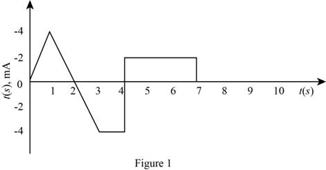
The expression for the current as a function of time is given by,
The slope of the line that represents the current from
The current for the time interval
The expression for the charge that flows through the wire for the time interval
Substitute
Conclusion:
Therefore, the charge that flows though the wire for the time interval
(b)
The charge that flows through the given time interval.
Answer to Problem 2.9HP
The charge that will flow through the wire form
Explanation of Solution
Calculation:
The given time interval is
The slope of the line that represents the current from
The conversion of
The conversion of
The conversion of
The current for the time interval
Substitute
Substitute
The expression for the charge stored from
Substitute
Substitute
Solve further as,
The expression for the charge stored from
Substitute
Substitute
Solve further as,
The mathematical expression for the straight line that represents the current waveform from
The expression for the charge stored from
Substitute
Solve further as,
The mathematical expression for the straight line that represents the current waveform from
The expression for the charge stored from
Substitute
The mathematical expression for the straight line that represents the current waveform from
The expression for the charge stored from
Substitute
The mathematical expression for the straight line that represents the current waveform from
The expression for the charge stored from
Substitute
The current is zero for
The expression for the charge stored from
Substitute
The charge stored from
Substitute
The charge stored from
Substitute
Conclusion:
Therefore, the charge that will flow through the wire form
(c)
To sketch:
The graph for
Answer to Problem 2.9HP
The sketch for
Explanation of Solution
Calculation:
The expression for the current for different time interval is given by,
The integration of the above equation with respect to time to obtain the charge expression is given by,
The evaluated form for the expression of charge for the different time interval is given by,
Substitute
Substitute
Substitute
Substitute
Substitute
Substitute
Substitute
Substitute
Substitute
Substitute
Substitute
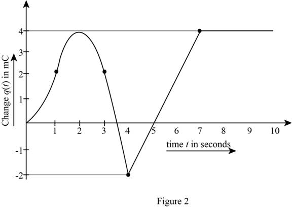
The sketch of
The required diagram is shown in Figure 2.
Want to see more full solutions like this?
Chapter 2 Solutions
Principles and Applications of Electrical Engineering


- A point charge of Q1 = 25nC is located at P1 (4,-2,7) while charge Q2 = 60nC is at P2 (-3,4,-2). If ∈=∈o?, find E at P3 (1,2,3)arrow_forward9. Write an equation to obtain the potential difference at point a with respect to point b, Vab? 10. What is the potential difference at point a with respect to point b, Vab?arrow_forwardConsidering that the power loss of a resistor is RI^2 and the information in the manual’s background section, derive an expression for the energy lost through Joule heating in a resistor when a capacitor completely discharges.arrow_forward
- Q1 For the figure shown below answer allthe following 1. Justtell without the details , how muuch work does t take to move a charge a long an equipotential ine from point ato point b ? S 3y fthe potentials are 50v, 15v, 30v. How much Va, VA, VI? And Why? 1£Va = 90v How much Vb2 And why? And how much the potential difference Vcd on the first equipotential line? FH 4.arrow_forwardIf a cell has an E.M.F of E volts, an internal resistance of r ohms and supplies A current I ampere to a load, the terminal p.d. V volts is given by....arrow_forwardA point charge of Q1 = 25nC is located at P1 (4,-2,7) while charge Q2 = 60nC is at P2 (-3,4,-2). If ∈=∈?, find E at P3 (1,2,3)arrow_forward
- In your own words, define a. an ideal conductor; b. an ideal voltage source; c. an ideal current source.arrow_forwardthe current (in mA) in each resistor shown in the figure aboveIR1IR2IR3 the potential difference between points c and f (Give the magnitude of your answer in volts and select the point of highest potential.) magnitude of potential difference What If? If all of the resistors in the circuit were decreased in value by a factor of 1,000, would the current in each resistor simply increase by a factor of 1,000? Explain your answer.arrow_forwardDiscussions:Voltage Distribution and String Efficiency of a Model Suspension Insulator 1- Comment on the results obtained.2- Give reasons for unequal potential distribution over the string.3- What is the effect of this un equality on the insulators?4- Can value of the string efficiency being equal to 100%. Explain your answer.5- Outline methods used to equalize the potential across the units.6- Why an insulator is represented as a capacitor C? What are the assumptionmodes?arrow_forward
- Answer the following point in detail and rigorously. Instead of resorting to formulas, develop from basic principles (laws of voltages and currents, definition of electrical power, among others). a) What meaning would you give to the P consumed by an element? Which to Q?arrow_forwarda rod of semiconducting meterial of length L = 2 m and cross-sectioanal area A=5mm2 lies along the x axis between x=0 and x=L. the meterial obeys Ohm's law, and its resistivity varies along the rod according to p=p0 (1-(x2/L2)) where p0=4,5 * 10-4 ohm*m. the end of the rod at x=0 is at a potential V0= 30 V greater than the end at x = L. a)what is the total resistance, in units of ohm, of the rod ? b)what is the current, in units of miliamperes in the rod? c)what is the electric potential, in units of Volt in the rod at x=L/2 ? d)what is the electric field magnitude E, in units of V/m, in the rod at x=L/2 ?arrow_forwardHow does the power, P, dissipated by a resistor depend on the indicated parameter (resistance, R,of the resistor, or the voltage or current of the supply) for each of the following scenarios? I amlooking for a mathematical equation for power as a function of the indicated parameter followed bya description of the dependence - does the power increase, decrease, remain the same or some otherdependence, as the parameter is increased? (and if other, describe.) If it is increasing or decreasing,by what factor does the power change if the parameter is increased by a factor of 3?(a) Constant R, powered by ideal voltage supply (We will examine real batteries that have internalresistance in class and the next homework.) How does P depend on the voltage, V, of thesupply?(b) Constant R, powered by ideal current supply. How does power depend on the current I?(c) Ideal battery operating at a fixed voltage, powering a variable resistor R. How does P dependon the resistance, R, of the resistor?(d)…arrow_forward
 Introductory Circuit Analysis (13th Edition)Electrical EngineeringISBN:9780133923605Author:Robert L. BoylestadPublisher:PEARSON
 Delmar's Standard Textbook Of ElectricityElectrical EngineeringISBN:9781337900348Author:Stephen L. HermanPublisher:Cengage Learning
 Programmable Logic ControllersElectrical EngineeringISBN:9780073373843Author:Frank D. PetruzellaPublisher:McGraw-Hill Education
 Fundamentals of Electric CircuitsElectrical EngineeringISBN:9780078028229Author:Charles K Alexander, Matthew SadikuPublisher:McGraw-Hill Education
 Electric Circuits. (11th Edition)Electrical EngineeringISBN:9780134746968Author:James W. Nilsson, Susan RiedelPublisher:PEARSON
 Engineering ElectromagneticsElectrical EngineeringISBN:9780078028151Author:Hayt, William H. (william Hart), Jr, BUCK, John A.Publisher:Mcgraw-hill Education,