
Concept explainers
Videos
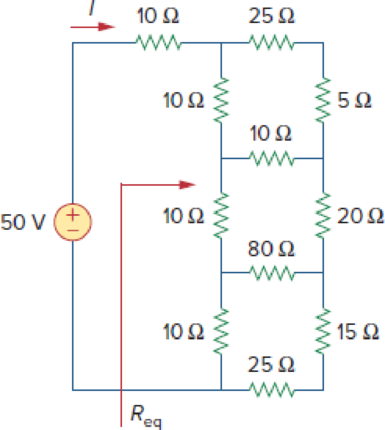
Find Req and I in the circuit of Fig. 2.121.
Figure 2.121
Calculate the values of equivalent resistance
Answer to Problem 57P
The values of equivalent resistance
Explanation of Solution
Formula used:
Consider the following delta to wye conversion, when all branches in a delta consist same value.
Consider the expression for
Here,
Consider the expression for
Calculation:
Refer to Figure 2.121 in the textbook For Prob.2.57.
Step 1:
In Figure 2.121, as
Step 2:
In Figure 2.121, as
Step 3:
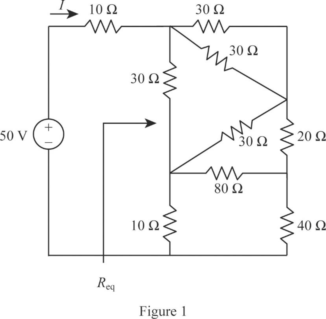
In Figure 2.121, convert the wye- sub network into delta connection.
Substitute
Since all branches values are same in a wye connection that is
Modify Figure 2.121 as shown in Figure 1.
Step 4:
In Figure 1, as
Modify Figure 1 as shown in Figure 2.
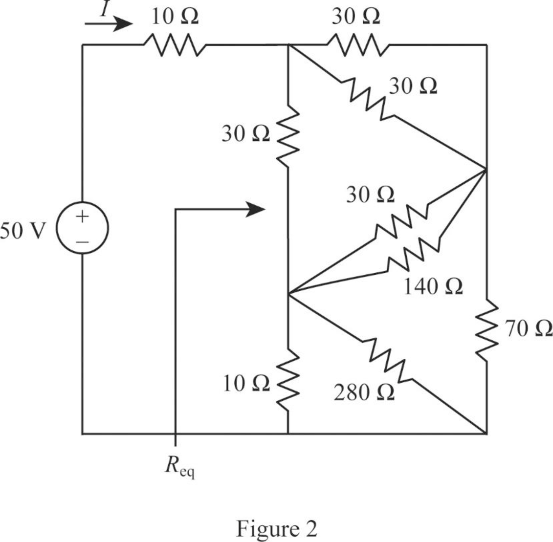
Step 5:
In Figure 2, as two
Step 6:
In Figure 2, as
Step 7:
In Figure 2, as
Modify Figure 2 as shown in Figure 3.
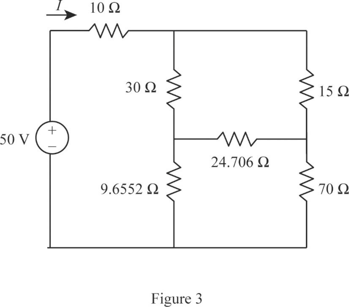
Step 8:
In Figure 3, as
Modify Figure 3 as shown in Figure 4.
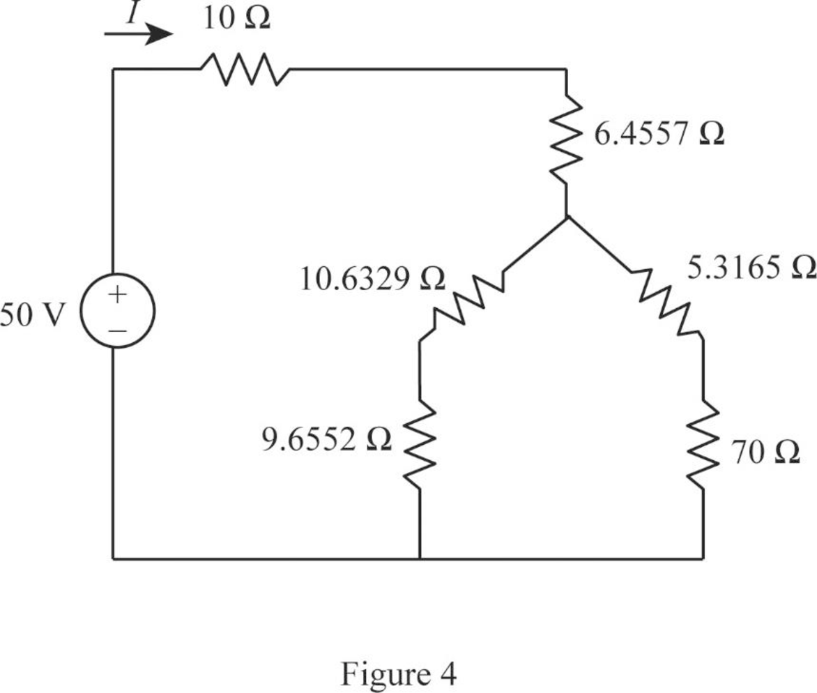
Step 9:
In Figure 4, as
Step 10:
In Figure 4, as
Step 11:
In Figure 4, as
Modify Figure 4 as shown in Figure 5.
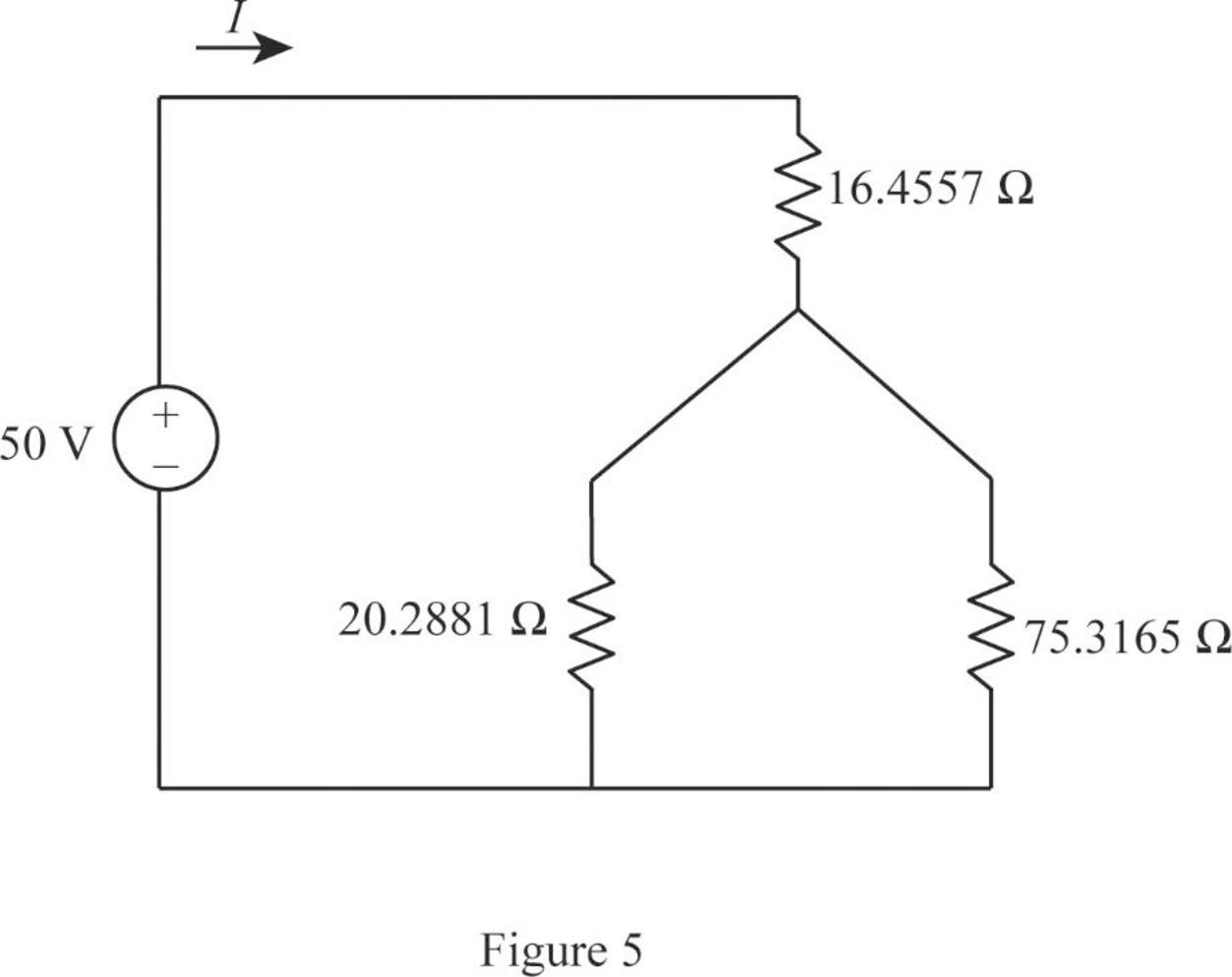
Step 12:
In Figure 5, as
Modify Figure 5 as shown in Figure 6.
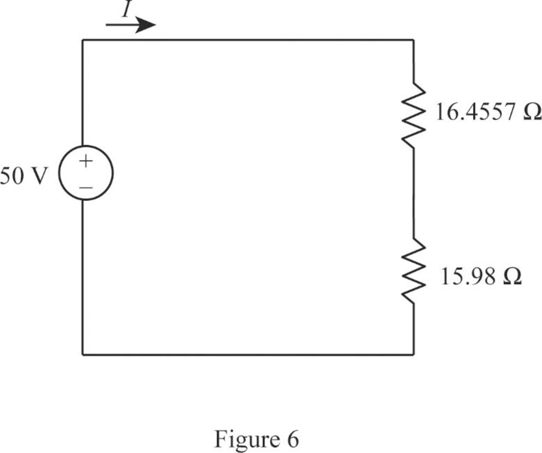
Step 13:
In Figure 6, as
Consider the general expression to find current
Conclusion:
Thus, the values of equivalent resistance
Want to see more full solutions like this?
Chapter 2 Solutions
FUNDAMENTALS OF ELEC.CIRC.(LL) >CUSTOM<
Additional Engineering Textbook Solutions
Electric Circuits (10th Edition)
Electrical Engineering: Principles & Applications (7th Edition)
Principles Of Electric Circuits
Microelectronics: Circuit Analysis and Design
Basic Engineering Circuit Analysis
ANALYSIS+DESIGN OF LINEAR CIRCUITS(LL)


- 4. Use source transformation technique to find the current flowing through the 2 Ω resistor in Fig. 2.87 (b). [10 A]arrow_forward3. By using repeated source transformations, find the value of voltage v in Fig. 2.87 (a). [8 V]arrow_forward9. In the network shown in Fig. 2.177 find the current that would flow if a 2-Ω resistor was connected between points A and B by using.(a) Thevenin’s theorem and (b) Superposition theorem. The two batteries have negligible resistance. [0.82 A]arrow_forward
- 7. Find the equivalent resistance between points A and B of the circuit shown in Fig. 2.198.arrow_forwardDetermine v, for each network of Fig. 2.157 for the input shown. 20 V 2V ldeal Ideal I ka 22 k2 -5 Varrow_forwardFrom fig.2, if a supply voltage of 16 V was connected across terminals A and B, computer for the overall power of the circuit.arrow_forward
- Which is the source to drain current of the circuit shown below? 158.3675 uA 1.34 uA 1.34 mA 324.1629 uAarrow_forward#2write your solution pls plsarrow_forward11. State and explain Superposition theorem. For the circuit of Fig. 2.126. (a) determine currents I1, I2 and I3 when switch S is in position b. (b) using the results of part (a) and the principle of superposition, determine the same currents with switch S in position a.[(a) 15 A, 10 A, 25 A (b) 11 A , 16 A, 27 A]arrow_forward
- An ideal voltmeter connected across terminal A and B of Fig.2 in will read – volt. *arrow_forward4. Find the equivalent Thevenin voltage and equivalent Thevenin resistance respectively as seen from open-circuited terminals A and B to the circuits shown in Fig. 2.173. All resistances are in ohms.arrow_forward2. Using mesh analysis, determine the voltage across the 10 kΩ resistor at terminals a-b of the circuit shown in Fig. 2.58.arrow_forward
 Introductory Circuit Analysis (13th Edition)Electrical EngineeringISBN:9780133923605Author:Robert L. BoylestadPublisher:PEARSON
 Delmar's Standard Textbook Of ElectricityElectrical EngineeringISBN:9781337900348Author:Stephen L. HermanPublisher:Cengage Learning
 Programmable Logic ControllersElectrical EngineeringISBN:9780073373843Author:Frank D. PetruzellaPublisher:McGraw-Hill Education
 Fundamentals of Electric CircuitsElectrical EngineeringISBN:9780078028229Author:Charles K Alexander, Matthew SadikuPublisher:McGraw-Hill Education
 Electric Circuits. (11th Edition)Electrical EngineeringISBN:9780134746968Author:James W. Nilsson, Susan RiedelPublisher:PEARSON
 Engineering ElectromagneticsElectrical EngineeringISBN:9780078028151Author:Hayt, William H. (william Hart), Jr, BUCK, John A.Publisher:Mcgraw-hill Education,