
Concept explainers
Videos
- (a) Obtain the voltage Vo in the circuit of Fig. 2.127(a).
- (b) Determine the voltage V′o measured when a voltmeter with 6-kΩ internal resistance is connected as shown in Fig. 2.127(b).
- (c) The finite resistance of the meter introduces an error into the measurement. Calculate the percent error as
- (d) Find the percent error if the internal resistance were 36 kΩ.
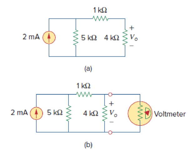
Figure 2.127
(a)
Find the value of voltage
Answer to Problem 67P
The value of voltage
Explanation of Solution
Calculation:
Refer to Figure 2.127(a) in the textbook.
Consider the current through
From current division rule, find the current through
From Ohms law, write the expression to find voltage across
Substitute
Conclusion:
Thus, the value of voltage
(b)
Find the voltage
Answer to Problem 67P
The voltage
Explanation of Solution
Calculation:
Refer to Figure 2.127(b) in the textbook.
In Figure 2.127(b), as internal resistance of
Consider the current through
From current division rule, find the current through
From Ohms law, write the expression to find voltage across
Substitute
Conclusion:
Thus, the voltage
(c)
Find the percent error.
Answer to Problem 67P
The error percent is
Explanation of Solution
Given data:
The expression for percent error is,
Calculation:
Substitute
Conclusion:
Thus, the error percent is
(d)
Find the percent error, when internal resistance is
Answer to Problem 67P
The error percentage, when internal resistance is
Explanation of Solution
Calculation:
Consider internal resistance as
Consider the current through
From current division rule, find the current through
From Ohms law, write the expression to find voltage across
Substitute
Substitute
Conclusion:
Thus, the error percent is
Want to see more full solutions like this?
Chapter 2 Solutions
Fundamentals of Electric Circuits


- 4. Use source transformation technique to find the current flowing through the 2 Ω resistor in Fig. 2.87 (b). [10 A]arrow_forward9. In the network shown in Fig. 2.177 find the current that would flow if a 2-Ω resistor was connected between points A and B by using.(a) Thevenin’s theorem and (b) Superposition theorem. The two batteries have negligible resistance. [0.82 A]arrow_forwardA copper conductor wire with a total length of 100ft is used in a 15 amp common household circuit has a resistance of 1.62 ohms/1000ft. If the circuit is fully loaded, approximate the resistance of the conductor? a. 129.6 ohms b. None of these c. 0.130 ohm d. 162 ohms e. 0.162 ohmarrow_forward
- A family of three is considering to install solar water heater system. Each person needs 50 liters of water per day. They require a hot water with temperature of 50 °C from using tap water as a source with a typical temperature of 20 °C. Calculate the required heat energy to satisfy the family demand in a year, and calculate the required area of flat plate collector (its efficiency 40% with energy gain 540 kWh.m-2/ year) and evacuated tube collector (its efficiency 60% with energy gain 800 kWh.m-2/ year) that needs to be installed. Describe your answer.arrow_forwardFrom fig.2, if a supply voltage of 16 V was connected across terminals A and B, computer for the overall power of the circuit.arrow_forward22. Determine the current i for the network shown in Fig. 2.48.arrow_forward
- 21. Find the value of the voltage v in the network of Fig. 2.47.arrow_forward6. If the terminals (negative and positive) of the power supply in Fig. 2.2 werereversed, it would be necessary to:A. Reverse the terminals of the ammeter and the resistor B. Reverse the terminals of the voltmeter and the ammeter C. Reverse the terminals of the voltmeter and the resistor D. Reverse the terminals of the resistor onlyarrow_forwardBasic Electrical Engineering A homeowner uses 100-watt incandescent lamps as a heater in an outside well pump house to protect the pump from freezing in cold weather. Unfortunately, however, the lamp can burn out and leave pump unprotected. You have been asked to install a hearth that will not burn out and leave the pump unprotected. You have available a 100-watt, 150-ohm wire-wound resistor. Can this resistor be connected to the 120-volt source without damage to the resistor? If so, what would be the power output of the resistor? (Hint: Use power formula)arrow_forward
- 9. Using KCL, find the values V,p, 1, 1 and I, in the circuit of Fig. 2.43. All resistances are in ohms. (YAp=12 V ; 1, =2/3 A; L, = 1A; I, = 4/3 AIarrow_forwardFor the network of Fig. 2.178: a. Calculate 5t. b. Compare 5t with half the period of the signal applied c. Draw vo.arrow_forwardDetermine VL, IL, IZ and IR for the network Figure 2.183 if RL = 180Ω.arrow_forward
 Introductory Circuit Analysis (13th Edition)Electrical EngineeringISBN:9780133923605Author:Robert L. BoylestadPublisher:PEARSON
 Delmar's Standard Textbook Of ElectricityElectrical EngineeringISBN:9781337900348Author:Stephen L. HermanPublisher:Cengage Learning
 Programmable Logic ControllersElectrical EngineeringISBN:9780073373843Author:Frank D. PetruzellaPublisher:McGraw-Hill Education
 Fundamentals of Electric CircuitsElectrical EngineeringISBN:9780078028229Author:Charles K Alexander, Matthew SadikuPublisher:McGraw-Hill Education
 Electric Circuits. (11th Edition)Electrical EngineeringISBN:9780134746968Author:James W. Nilsson, Susan RiedelPublisher:PEARSON
 Engineering ElectromagneticsElectrical EngineeringISBN:9780078028151Author:Hayt, William H. (william Hart), Jr, BUCK, John A.Publisher:Mcgraw-hill Education,