
Concept explainers
Videos
Obtain the equivalent resistance at the terminals a-b for each of the circuits in Fig. 2.115.
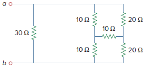
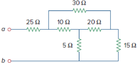
Figure 2.115
(a)
Calculate the equivalent resistance at terminals a-b in Figure 2.115(a).
Answer to Problem 51P
The equivalent resistance at terminals a-b in Figure 2.115(a) is
Explanation of Solution
Formula used:
Consider the following delta to wye conversion, when all branches in a delta consists same value.
Consider the expression for
Here,
Consider the expression for
Calculation:
Refer to Figure 2.115(a) in the textbook For Prob.2.51.
Step 1:
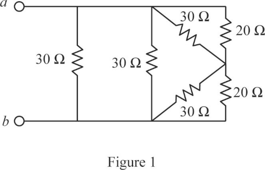
In Figure 2.115(a), convert the wye connection into delta connection.
Substitute
Since all branches values are same in a wye connection that is
Modify Figure 2.115(a) as shown in Figure 1.
Step 2:
In Figure 1, as
Step 3:
In Figure 1, as
Step 4:
In Figure 1, as
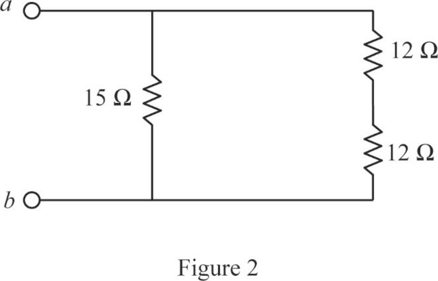
Modify Figure 1 as shown in Figure 2.
Step 5:
In Figure 2, as two
Modify Figure 2 as shown in Figure 3.
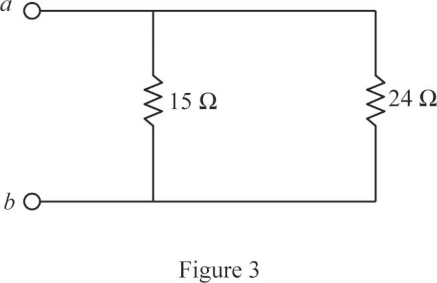
Step 6:
In Figure 3, as
Conclusion:
Thus, the equivalent resistor at terminals a-b in Figure 2.115(a) is
(b)
Calculate the equivalent resistance at terminals a-b in Figure 2.115(b).
Answer to Problem 51P
The equivalent resistance at terminals a-b in Figure 2.115(b) is
Explanation of Solution
Formula used:
Consider the wye to delta conversions.
Here,
Calculation:
Refer to Figure 2.115(b) in the textbook For Prob.2.51.
Step 1:
In Figure 2.115(a), convert the wye connection
Consider
Substitute
Substitute
Substitute
Modify Figure 2.115(b) as shown in Figure 4.
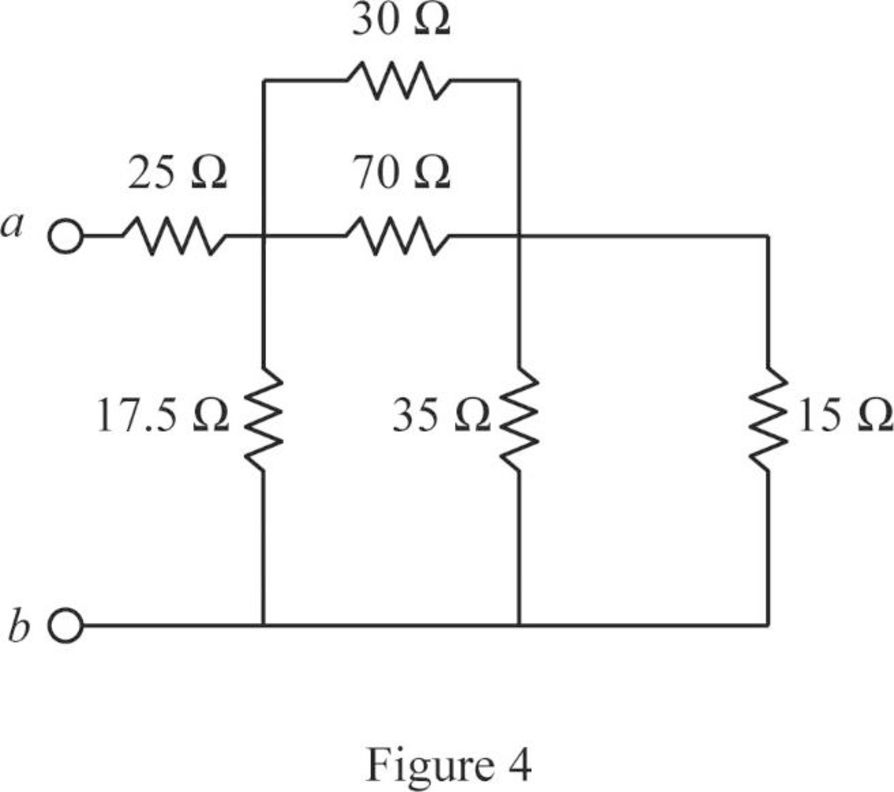
Step 2:
In Figure 4, as
Step 3:
In Figure 4, as
Modify Figure 4 as shown in Figure 5.
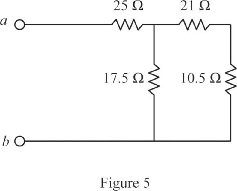
Step 4:
In Figure 5, as
Modify Figure 5 as shown in Figure 6.
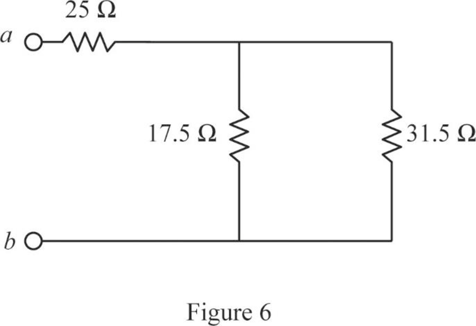
Step 5:
In Figure 6, as
Conclusion:
Thus, the equivalent resistor at terminals a-b in Figure 2.115(b) is
Want to see more full solutions like this?
Chapter 2 Solutions
Fundamentals of Electric Circuits


- 9. In the network shown in Fig. 2.177 find the current that would flow if a 2-Ω resistor was connected between points A and B by using.(a) Thevenin’s theorem and (b) Superposition theorem. The two batteries have negligible resistance. [0.82 A]arrow_forwardAn ideal voltmeter connected across terminal A and B of Fig.2 in will read – volt. *arrow_forwardDetermine v, for each network of Fig. 2.157 for the input shown. 20 V 2V ldeal Ideal I ka 22 k2 -5 Varrow_forward
- A family of three is considering to install solar water heater system. Each person needs 50 liters of water per day. They require a hot water with temperature of 50 °C from using tap water as a source with a typical temperature of 20 °C. Calculate the required heat energy to satisfy the family demand in a year, and calculate the required area of flat plate collector (its efficiency 40% with energy gain 540 kWh.m-2/ year) and evacuated tube collector (its efficiency 60% with energy gain 800 kWh.m-2/ year) that needs to be installed. Describe your answer.arrow_forwardDetermine VL, IL, IZ and IR for the network Figure 2.183 if RL = 180Ω.arrow_forward3. Determine the resistance between points A and B in the network of Fig. 2.195.arrow_forward
- 5. Using delta/star transformation determine the current through the galvanometer in the Wheatstone bridge of Fig. 2.196.arrow_forward4. Use source transformation technique to find the current flowing through the 2 Ω resistor in Fig. 2.87 (b). [10 A]arrow_forward21. Find the value of the voltage v in the network of Fig. 2.47.arrow_forward
 Introductory Circuit Analysis (13th Edition)Electrical EngineeringISBN:9780133923605Author:Robert L. BoylestadPublisher:PEARSON
 Delmar's Standard Textbook Of ElectricityElectrical EngineeringISBN:9781337900348Author:Stephen L. HermanPublisher:Cengage Learning
 Programmable Logic ControllersElectrical EngineeringISBN:9780073373843Author:Frank D. PetruzellaPublisher:McGraw-Hill Education
 Fundamentals of Electric CircuitsElectrical EngineeringISBN:9780078028229Author:Charles K Alexander, Matthew SadikuPublisher:McGraw-Hill Education
 Electric Circuits. (11th Edition)Electrical EngineeringISBN:9780134746968Author:James W. Nilsson, Susan RiedelPublisher:PEARSON
 Engineering ElectromagneticsElectrical EngineeringISBN:9780078028151Author:Hayt, William H. (william Hart), Jr, BUCK, John A.Publisher:Mcgraw-hill Education,