
Loose Leaf for Shigley's Mechanical Engineering Design Format: LooseLeaf
10th Edition
ISBN: 9780073399652
Author: BUDYNAS
Publisher: Mcgraw Hill Publishers
expand_more
expand_more
format_list_bulleted
Concept explainers
Videos
Textbook Question
Chapter 20, Problem 14P
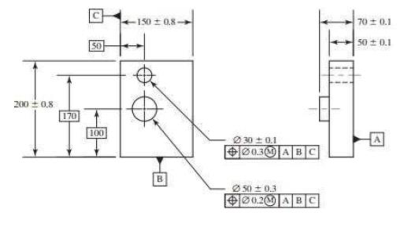
For the part shown, answer the following questions with regard to the hole.
- (a) What are the maximum and minimum diameters allowed for the hole?
- (b) What is the effect of the position tolerance of 0.3 on the diameters specified in part (a)?
- (c) The position control defines a tolerance zone. Specifically what must stay within that tolerance zone?
- (d) What is the diameter of the tolerance zone if the hole is produced with a diameter of 30.1?
- (e) What is the diameter of the tolerance zone if the hole is produced with a diameter of 29.9?
- (f) Describe the significance of the datum references to the determination of the position tolerance zone.
- (g) What is the perpendicularity tolerance with respect to datum A? (Select one.)
- i. Not defined.
- ii. Controlled by the position tolerance; 0.3.
- iii. Controlled by the size tolerance; 0.1.
- iv. Must be perfectly perpendicular; 0.
- (h) What controls the cylindricity? (Select one.)
- i. There is no control on the cylindricity.
- ii. From Rule #1, the envelope of a perfect cylinder with diameter of 30.
- iii. From Rule #1, the envelope of a perfect cylinder with diameter of 29.9.
- iv. From the position control, the center axis of each cross section must be within the 0.3 cylindrical tolerance zone.
Expert Solution & Answer
Want to see the full answer?
Check out a sample textbook solution
Students have asked these similar questions
Given a pin with a size dimension of Ø.875±.003 and a perpendicularity tolerance of .002 at MMC to a primary datum, what is the boundary that takes into consideration the combined effect of feature size at MMC and the geometric tolerance?
.870
.874
.876
.880
I need help please.
Apply a dia 0.5 at MMC straightness control to the axis of the part above and draw the resultant tolerance zone and virtual size on the sketch of the produced part below.
The image and question are also attached.
Please answer #83
82.Given a Ø24±0.25 hole located with a positional tolerance at LMC of Ø0.15, what is the positional tolerance at a produced size of Ø23.75?
0.15
0.25
0.40
0.65
83.What is the minimum edge distance between the surface of the hole in Question 82 and the outside surface of the part if the location dimension is 40 mm?
28.05
27.8
27.475
25.875
Chapter 20 Solutions
Loose Leaf for Shigley's Mechanical Engineering Design Format: LooseLeaf
Ch. 20 - In the traditional coordinate dimensioning system,...Ch. 20 - Prob. 2PCh. 20 - Prob. 3PCh. 20 - What is the term that refers to a feature which...Ch. 20 - What are the four geometric attributes that must...Ch. 20 - Prob. 6PCh. 20 - What are the three geometric characteristics that...Ch. 20 - What are the three geometric characteristics that...Ch. 20 - How is a basic dimension toleranced? (Select one.)...Ch. 20 - Prob. 10P
Ch. 20 - For the part shown, clearly identify each of the...Ch. 20 - Prob. 12PCh. 20 - For the part shown, answer the following questions...Ch. 20 - For the part shown, answer the following questions...Ch. 20 - Prob. 15PCh. 20 - Prob. 16PCh. 20 - Prob. 17PCh. 20 - Prob. 18PCh. 20 - Prob. 19PCh. 20 - A shaft diameter is dimensioned 20 0.2. According...Ch. 20 - Prob. 21PCh. 20 - Prob. 22PCh. 20 - Prob. 23PCh. 20 - Prob. 24PCh. 20 - Which geometric characteristics never reference...Ch. 20 - Answer the following questions regarding material...Ch. 20 - The drawing shown is of a mounting fixture to...
Knowledge Booster


Learn more about
Need a deep-dive on the concept behind this application? Look no further. Learn more about this topic, mechanical-engineering and related others by exploring similar questions and additional content below.Similar questions
- Which variant of defining dimensions (A or B) would allow a higher overall part length tolerance, if the title block of the drawing holds an entry “General tolerances according to ISO 2768-m)”? Explain the reason for your answer.arrow_forwardPlease Fill In the blanks where I have marked red X's using the questions and Image below. 1. On the drawing above, before any geometric controls are applied, what is the coaxility tolerance is implied between the diameters? 2. On the part above, apply datum feature symbols to create a datum axis A-B by using the right and left diamters. 3. Apply a position coaxility between the right and left diamter of 0.1 at MMC. 4. Apply a position tolerance to the large center diameter within a diameter of 0.3 in relation to the single datum axis established by both datum features A and B.arrow_forward1. a. On the part shown, show a angularity specification to orient the angled surface in relation to the right surface in the side view and top surface in the front view within .005 total. Make sure to label the datum features. b. Shoudl the 25 degree angle above have a plus/minus tolerance applied or should it be basic? Complete this requirement on the drawing. c. What is the flatness tolerance on the angled surface above?arrow_forward
- Which position tolerance is shown in below’s technical drawing? Explain the meaning (that is the definition) of this tolerancearrow_forwardResearch and identify one type of geometric tolerances (besides obvious specs like length, distance, diameter, etc.) that can be called out on a technical drawing. Explain how this tolerance is definedarrow_forwardII. Provide complete solutions per problem. No need to copy the problem butprovide the ff format: (a) given (b) required (c)solution 2. A medium force fit on a 75 mm shaft requires a hole tolerance and shaft tolerance eachequal to 0.225 mm and average interference of 0.0375 mm. Find the hole and shaftdimensions.arrow_forward
- For the following part sizes and geometric tolerances, determine the appropriate geometric tolerance for each discrete part size and calculate the virtual condition.arrow_forwardApply geometric tolerancing to part according to the instructions below. This exercise will provide you with experience in correctly applying and interpreting geometric tolerancing symbology. If you have trouble applying the symbols, page through this unit looking for similar examples. The Hole Bar in this unit is a good reference. Draw symbols and feature control frames clearly and neatly. 1. Establish the right face in the side view as datum feature A. Qualify this feature with a flatness of .005. 2. Establish the top surface in the front view as datum feature B. Qualify this feature with a perpendicularity of .005 to datum feature A. 3. Establish the left surface in the front view as datum feature C. Qualify this feature with a perpendicularity of .005 to datum features A and B. 4. Establish all necessary dimensions as basic. 5. Position the .250 hole within a diameter of .005 RFS relative to datum features A,B,C. 6. Position the three holes within a diamter of .012 at MMC relative…arrow_forwardApply geometric tolerancing to part according to the instructions below. This exercise will provide you with experience in correctly applying and interpreting geometric tolerancing symbology. If you have trouble applying the symbols, page through this unit looking for similar examples. The Hole Bar in this unit is a good reference. Draw symbols and feature control frames clearly and neatly. 1. Establish the right face in the side view as datum feature A. Qualify this feature with a flatness of .005. 2. Establish the top surface in the front view as datum feature B. Qualify this feature with a perpendicularity of .005 to datum feature A. 3. Establish the left surface in the front view as datum feature C. Qualify this feature with a perpendicularity of .005 to datum features A and B. Please refer to the attached image.arrow_forward
- 1. How much position toleranceis allowed if the 3 holes are produced at a size of 14.8 mm? And how much position tolerance is allowed if the 3 holes are produced at a size of 15 mm? 2. What is the perpendicularity tolerance to datum A for the 3 holes? And what could be the maximum perpendicularity tolerance on the center hole? 3. Does the 94 mm bolt circle dimension have tolerance? if so, what is it. I need help with these. Please refer to image as a reference.arrow_forwardRefer to the Ø.8740 ± .0005 dimension. D) What is the MMC,(Maximum material condition) ? ________________________________ E) What is the LMC,?(least material condition) _________________________________ Refer to the 1.914 dimension. Where is the tolerance specified ? _________________________________arrow_forwardRefer to the 1.914 dimension. A) Where is the tolerance specified ? _________________________________ B) What is its tolerance ? ________________________________C) What is the MMC? ______________________________ D) What is the LMC? _______________________________arrow_forward
arrow_back_ios
SEE MORE QUESTIONS
arrow_forward_ios
Recommended textbooks for you
 Welding: Principles and Applications (MindTap Cou...Mechanical EngineeringISBN:9781305494695Author:Larry JeffusPublisher:Cengage Learning
Welding: Principles and Applications (MindTap Cou...
Mechanical Engineering
ISBN:9781305494695
Author:Larry Jeffus
Publisher:Cengage Learning
LIMITS FITS AND TOLERANCES: What is limit fit & tolerance and its need? Animation; Author: ADTW learn;https://www.youtube.com/watch?v=joBy4BoJszo;License: Standard YouTube License, CC-BY
Limits and Continuity; Author: The Organic Chemistry Tutor;https://www.youtube.com/watch?v=9brk313DjV8;License: Standard YouTube License, CC-BY