
Introductory Circuit Analysis; Laboratory Manual For Introductory Circuit Analysis Format: Kit/package/shrinkwrap
13th Edition
ISBN: 9780134297446
Author: Boylestad, Robert L.
Publisher: Prentice Hall
expand_more
expand_more
format_list_bulleted
Concept explainers
Videos
Textbook Question
Chapter 21, Problem 13P
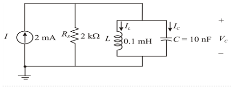
For the “ideal” parallel resonant circuit in Fig. 21 .54:
a. Determine the resonant frequency (fp).
b. Find the voltage Vc at resonance.Â
c. Determine the currents IL and Ic at resonance.
d. Find Qp.
Expert Solution & Answer
Want to see the full answer?
Check out a sample textbook solution
Students have asked these similar questions
7. a. The bandwidth of a series resonant circuit is 200 Hz.
If the resonant frequency is 2000 Hz, what is the
value of Q. for the circuit?
b. If R = 22, what is the value of X₂ at resonance?
c. Find the value of L and C at resonance.
d. Find the cutoff frequencies.
Calculate the gain at -3dB in dB.
A Parallel Resonant ckt is given in the figure. Calculate Wo, W1, W2 , QF & Bw.
Chapter 21 Solutions
Introductory Circuit Analysis; Laboratory Manual For Introductory Circuit Analysis Format: Kit/package/shrinkwrap
Ch. 21 - Find the resonant s and fs for the series circuit...Ch. 21 - For the senes circuit in Fig. 21.51 : a. Find the...Ch. 21 - For the senes circuit in Fig. 21.52 : a. Find the...Ch. 21 - For the circuit in Fig. 21.53: a. Find the value...Ch. 21 - a. Find the bandwidth of a series resonant circuit...Ch. 21 - A series circuit has a resonant frequency of 10...Ch. 21 - a. The bandwidth of a series resonant circuit is...Ch. 21 - The cutoff frequencies of a series resonant...Ch. 21 - a. Design a series resonant circuit with an input...Ch. 21 - Design a series resonant circuit to have a...
Ch. 21 - A series resonant circuit is to resonate at s=2106...Ch. 21 - Prob. 12PCh. 21 - For the ideal parallel resonant circuit in Fig. 21...Ch. 21 - For the parallel resonant network in Fig. 21.55:...Ch. 21 - The network of Fig. 21.56 has a supply with an...Ch. 21 - For the network in Fig. 21.57: a. Find the value...Ch. 21 - The network shown in Fig. 21.58 is to resonate at...Ch. 21 - For the network in Fig. 21.59: a. Find the...Ch. 21 - Prob. 19PCh. 21 - It is desired that the impedance ZT of the high Q...Ch. 21 - For the network in Fig. 21.62: a. Find fp. b....Ch. 21 - For the network in Fig. 21.63: a. Find the value...Ch. 21 - Prob. 23PCh. 21 - For the network in Fig. 21.65: a. Find fs. fp, and...Ch. 21 - For the network in Fig. 21.66, the following are...Ch. 21 - Prob. 26PCh. 21 - For the parallel resonant circuit in Fig. 21.68:...Ch. 21 - Verify the results in Example 21.8, That is, show...Ch. 21 - Find fp and fm for the parallel resonant network...
Additional Engineering Textbook Solutions
Find more solutions based on key concepts
Find I0 and I1 in the circuit in Fig.P2.12.
Basic Engineering Circuit Analysis
Identify the type of input and output configuration for each diff-amp in Figure 18-35.
Electronics Fundamentals: Circuits, Devices & Applications
Design an ideal inverting op-amp circuit such that the voltage gain is Av=25 . The maximum current in any resis...
Microelectronics: Circuit Analysis and Design
Does the severity of an electric shock increase ordecrease with eh of the following changes? a. A decrease in t...
Electric Motors and Control Systems
Assume a telephone signal travels through a cable at two-thirds the speed of light. How long does it take the s...
Electric Circuits (10th Edition)
The current source in the circuit shown generates the current pulse
Find (a) v (0); (b) the instant of time gr...
Electric Circuits. (11th Edition)
Knowledge Booster


Learn more about
Need a deep-dive on the concept behind this application? Look no further. Learn more about this topic, electrical-engineering and related others by exploring similar questions and additional content below.Similar questions
- 21.5 For a series RLC circuit. a) Find the bandwidth of a series resonant circuit having a resonant frequency of 6000 Hz and a Q of 15. b) Find the cutoff frequencies. c) If the resistance of the circuit at resonance 32, what are the values of X, and Xc in ohms? d) What is the power dissipated at the half-power frequencies if the maximum current flowing through the circuit is 0.5 Amps?arrow_forwardFind the resonant frequency for the network below. The circuit is energized by a 24-Vac,variable frequency supply. Then, for the resonant condition calculate the circuitimpedance and current.arrow_forwardPlease design the filter according to the questionarrow_forward
- Calculate the resonant frequency of the median resonator. The value of D2= 6.05 cm, D1= 1.72 cm,Lreal= 1.89 cm and the temperature is 25°. Also obtain the value in units of the frequency ofresonance.arrow_forwardDiscuss the difference between resonant and nonresonant circuitsarrow_forward2. In each case, what will be the frequency in the square wave and the sampling rate you will choose in your experiment? 3. Sketch the voltages on R and C for 2 period of the square wave, label your time axis with value and unit. 4. repeat step 4 for RL circuit.arrow_forward
- LAB 1 Questions R Vout Vin 1. Find H(w) = Vo/Vi. 2. Derive an expression for the cutoff frequency. 3. Calculate the output voltage at frequencies: 50 Hz, 100 Hz, 150 Hz, 200 Hz, 300 Hz and 1KHZ. Assume Vin=4 v (peak-to-peak), R=1.1 k and C=1uF. 4. Calculate the cutoff frequency and the output voltage at this value.arrow_forwardFor the following given circuit; b) find Av and Avs in the medium frequency range.c) find fHi and fh0.d) draw the frequency response for the high frequency region using the bode graph and determine the cutting frequency.arrow_forward(b) In a filter, explain what happens at the cut–off frequency.arrow_forward
- P3 For the series RLC circuit given in Figure 4 for Vs=10sinot R=2.2 2, L=100 uH and C=1000 uF a) Obtain the resonant frequency and the half-power frequencies. b) Calculate the quality factor and bandwidth. c) Determine the amplitude of the current at 60, 6 and 02. d) Plot the current amplitude versus frequency e) Use LTSPICE to plot frequency response.arrow_forward*9. Design a series resonant circuit with an input voltage of 5 V 20° to have the following specifications: a. A peak current of 500 mA at resonance b. A bandwidth of 120 Hz c. A resonant frequency of 8400 Hz Find the value of L and C and the cutoff frequencies.arrow_forwardQ.5: b. Choose the suitable choice for nine of the following sentences. 1. In order to lune a parallel resonant circuit to a lower frequency. the capacitor must........ > Be decrease. a. Be increase d. Remain the same. e. Be Zero. 2 In series as well as parallel resonance circuit, increase in resistance would cause the bandwidth is...... a. Increase in both circuits. (h. Decrease in series eircuit and increase in parallel circuit. d. lucrease in series circuit and decrease in parallel circuit. circuit. e Decrease in both circuits. 3. In a very low frequency a series resonance circuit behaves as almost purely a. Resistive. c. Inductive. d. Inductive and capacitive. b. Capacitive: 4. Real part of the total impedance at resonance for complicated AC circuit is a. Positive Value. b. Zero Value. 5. For admittance locus the maximum obtained power factor is depend on: a. Maximum current b. Maximum voltage c. Minimum power 4. Minimum angle 6. Any non-sinusoidal symmetrical waves are basically…arrow_forward
arrow_back_ios
SEE MORE QUESTIONS
arrow_forward_ios
Recommended textbooks for you
 Introductory Circuit Analysis (13th Edition)Electrical EngineeringISBN:9780133923605Author:Robert L. BoylestadPublisher:PEARSON
 Delmar's Standard Textbook Of ElectricityElectrical EngineeringISBN:9781337900348Author:Stephen L. HermanPublisher:Cengage Learning
 Programmable Logic ControllersElectrical EngineeringISBN:9780073373843Author:Frank D. PetruzellaPublisher:McGraw-Hill Education
 Fundamentals of Electric CircuitsElectrical EngineeringISBN:9780078028229Author:Charles K Alexander, Matthew SadikuPublisher:McGraw-Hill Education
 Electric Circuits. (11th Edition)Electrical EngineeringISBN:9780134746968Author:James W. Nilsson, Susan RiedelPublisher:PEARSON
 Engineering ElectromagneticsElectrical EngineeringISBN:9780078028151Author:Hayt, William H. (william Hart), Jr, BUCK, John A.Publisher:Mcgraw-hill Education,
Introductory Circuit Analysis (13th Edition)
Electrical Engineering
ISBN:9780133923605
Author:Robert L. Boylestad
Publisher:PEARSON
Delmar's Standard Textbook Of Electricity
Electrical Engineering
ISBN:9781337900348
Author:Stephen L. Herman
Publisher:Cengage Learning
Programmable Logic Controllers
Electrical Engineering
ISBN:9780073373843
Author:Frank D. Petruzella
Publisher:McGraw-Hill Education
Fundamentals of Electric Circuits
Electrical Engineering
ISBN:9780078028229
Author:Charles K Alexander, Matthew Sadiku
Publisher:McGraw-Hill Education
Electric Circuits. (11th Edition)
Electrical Engineering
ISBN:9780134746968
Author:James W. Nilsson, Susan Riedel
Publisher:PEARSON
Engineering Electromagnetics
Electrical Engineering
ISBN:9780078028151
Author:Hayt, William H. (william Hart), Jr, BUCK, John A.
Publisher:Mcgraw-hill Education,
What is Filter & Classification of Filters | Four Types of Filters | Electronic Devices & Circuits; Author: SimplyInfo;https://www.youtube.com/watch?v=9x1Sjz-VPSg;License: Standard Youtube License