
Electronics Fundamentals: Circuits, Devices & Applications
8th Edition
ISBN: 9780135072950
Author: Thomas L. Floyd, David Buchla
Publisher: Prentice Hall
expand_more
expand_more
format_list_bulleted
Concept explainers
Videos
Textbook Question
Chapter 21, Problem 16P
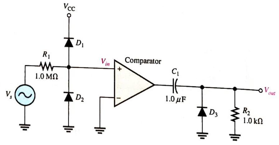
For the circuit in Figure 21-53, describe the waveform at the output of the comparator and at the output of the circuit in relation to the input. Assume the input is a 120 V rms sine wave the comparator and the power supply voltages for the comparator are
Expert Solution & Answer
Want to see the full answer?
Check out a sample textbook solution
Students have asked these similar questions
-Fill in the blank(s) with appropriate word(s):
1. The three –phase half - wave converter is not normally used in practical systems, because ___________________.2. The three –phase half - wave converter is provide _______________average output voltage.3. The frequency of output ripple voltage for three –phase half - wave converter is_____________.
: Determine the peak value of the output voltage for Figure. if the turns ratio is 3:1.
The input voltage of the buck converter should be 100 and the output voltage should be 60. The switching frequency is 10khz and the coil value is 3mH. What is the required capacity value for the output voltage ripple to be 10v?
Chapter 21 Solutions
Electronics Fundamentals: Circuits, Devices & Applications
Ch. 21 - A thermocouple can measure higher temperatures...Ch. 21 - Thermocouples are commonly used to measure body...Ch. 21 - An advantage of an RTD over a thermistor is that...Ch. 21 - Prob. 4TFQCh. 21 - A thermocouple signal conditioner must have high...Ch. 21 - Signal conditioning for temperature sensors...Ch. 21 - Prob. 7TFQCh. 21 - Absolute pressure is measured relative to the...Ch. 21 - In a sample-and-hold circuit, an analog value is...Ch. 21 - Prob. 10TFQ
Ch. 21 - A thermocouple a change in resistance for a change...Ch. 21 - In a thermocouple circuit, where each of the...Ch. 21 - A thermocouple signal conditioner is designed to...Ch. 21 - Prob. 4STCh. 21 - Prob. 5STCh. 21 - Prob. 6STCh. 21 - Prob. 7STCh. 21 - Prob. 8STCh. 21 - Prob. 9STCh. 21 - Prob. 10STCh. 21 - Prob. 11STCh. 21 - Prob. 12STCh. 21 - Prob. 13STCh. 21 - Prob. 14STCh. 21 - In an analog switch, the aperture time is the time...Ch. 21 - Prob. 16STCh. 21 - An analog signal must be sampled at a minimum rate...Ch. 21 - Prob. 18STCh. 21 - Prob. 19STCh. 21 - Prob. 20STCh. 21 - Prob. 21STCh. 21 - Three identical thermocouples are each exposed to...Ch. 21 - You have two thermocouples. One is a K type and...Ch. 21 - Determine the output voltage of the op-amp in...Ch. 21 - What should be the output voltage in Problem 3 if...Ch. 21 - Prob. 5PCh. 21 - Prob. 6PCh. 21 - Explain the difference in the results of Problems...Ch. 21 - Prob. 8PCh. 21 - A certain material being measured undergoes a...Ch. 21 - Explain how a strain gauge can be used to measure...Ch. 21 - Identify and compare the three symbols in Figure...Ch. 21 - Determine the output voltage waveform for the...Ch. 21 - Repeat Problem 12 for the waveforms in Figure...Ch. 21 - Name two ways an SCR can be placed in the...Ch. 21 - Sketch the VR waveform for the circuit in Figure...Ch. 21 - For the circuit in Figure 21-53, describe the...Ch. 21 - What change to the circuit in Figure 21-53 would...
Knowledge Booster


Learn more about
Need a deep-dive on the concept behind this application? Look no further. Learn more about this topic, electrical-engineering and related others by exploring similar questions and additional content below.Similar questions
- A DC-DC buck converter operates in continuous conduction mode. It has 48 V input voltage, and it feeds a resistive load of 24 Ω . The switching frequency of the converter is 250 Hz. If switch-on duration is 1 ms, the load power isarrow_forwardDetermine the waveform of the peak output voltage at Resistor L. The winding ratio is 5:1 (gives an output of 20%).arrow_forwardWhat is the average value of a half-wave rectified voltage with a peak value of 400 V? Draw its output waveform.arrow_forward
- Discuss the following a. Digital to Analog and Analog to Digital Converter b. Phase Locked Looparrow_forwardA Voltage Event Recorder (VER) is a device that records voltage fluctuations.arrow_forwardat MatchingTechniques What is the difference between 1. Quarter-WaveTransformer.2.StubTuningarrow_forward
- Qx Draw the output voltage (V) of the circuit shown in figure (1. for the input voltage. =+ 13Sinwtarrow_forwardA 1 - ∅ full-wave rectifier is made by using thyristors. If the peak value of the sinusoidal input voltage is Vm and the value of the delay angle is 45 degree, find the average value of output voltage Select one: a. 0.65 VM b. 0.85 VM c. 0.45 VM d. 0.25 Vmarrow_forwardFind value of K so that the system has: Percent Overshoot less than or equal to 22% 0 to 100 Rise Time less than or equal to 1 ms Peak Time less than or equal to 15 msarrow_forward
- Question 1 Base on Statcom a)Draw the block diagram of the STATCOM b) Give the operating mode of the STATCOM c) Draw the V-1 characteristic of the STATCOMarrow_forward3.Explain about Lead compensator and Lag compensator in detailarrow_forwardA boost converter is 80% efficient, has an output voltage of 12V and a duty cycle of 75%. What is the input voltage?arrow_forward
arrow_back_ios
SEE MORE QUESTIONS
arrow_forward_ios
Recommended textbooks for you
 Introductory Circuit Analysis (13th Edition)Electrical EngineeringISBN:9780133923605Author:Robert L. BoylestadPublisher:PEARSON
 Delmar's Standard Textbook Of ElectricityElectrical EngineeringISBN:9781337900348Author:Stephen L. HermanPublisher:Cengage Learning
 Programmable Logic ControllersElectrical EngineeringISBN:9780073373843Author:Frank D. PetruzellaPublisher:McGraw-Hill Education
 Fundamentals of Electric CircuitsElectrical EngineeringISBN:9780078028229Author:Charles K Alexander, Matthew SadikuPublisher:McGraw-Hill Education
 Electric Circuits. (11th Edition)Electrical EngineeringISBN:9780134746968Author:James W. Nilsson, Susan RiedelPublisher:PEARSON
 Engineering ElectromagneticsElectrical EngineeringISBN:9780078028151Author:Hayt, William H. (william Hart), Jr, BUCK, John A.Publisher:Mcgraw-hill Education,
Introductory Circuit Analysis (13th Edition)
Electrical Engineering
ISBN:9780133923605
Author:Robert L. Boylestad
Publisher:PEARSON
Delmar's Standard Textbook Of Electricity
Electrical Engineering
ISBN:9781337900348
Author:Stephen L. Herman
Publisher:Cengage Learning
Programmable Logic Controllers
Electrical Engineering
ISBN:9780073373843
Author:Frank D. Petruzella
Publisher:McGraw-Hill Education
Fundamentals of Electric Circuits
Electrical Engineering
ISBN:9780078028229
Author:Charles K Alexander, Matthew Sadiku
Publisher:McGraw-Hill Education
Electric Circuits. (11th Edition)
Electrical Engineering
ISBN:9780134746968
Author:James W. Nilsson, Susan Riedel
Publisher:PEARSON
Engineering Electromagnetics
Electrical Engineering
ISBN:9780078028151
Author:Hayt, William H. (william Hart), Jr, BUCK, John A.
Publisher:Mcgraw-hill Education,
ME32 Wheatstone Bridge Method; Author: Lectures in Electrical Engineering;https://www.youtube.com/watch?v=p8iTTpzMR38;License: Standard YouTube License, CC-BY