
Videos
Two forces are applied as shown to a hook. Determine graphically the magnitude and direction of their resultant using (a) the parallelogram law, (b) the triangle rule.
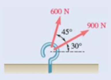
Fig. P2.1
(a)
The magnitude and direction of the resultant force on the hook graphically using the parallelogram law.
Answer to Problem 2.1P
The magnitude of the resultant force on the hook determined graphically using the parallelogram law is
Explanation of Solution
Force is a vector and the addition of vectors can be done using parallelogram law. The parallelogram law of vector addition says that if a parallelogram is constructed using two vectors by taking them as the adjacent sides of the parallelogram by attaching them on the same point, then the diagonal passing through that point gives the sum of the two vectors.
The forces acting on the hook are taken as the adjacent sides of the parallelogram. The diagram is shown in figure 1. In the figure,
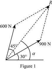
The length of the diagonal of the parallelogram gives the magnitude of the resultant vector and the angle the diagonal makes with the horizontal gives the direction.
Conclusion:
The length of the diagonal is measured to be
Thus, the magnitude of the resultant force on the hook determined graphically using the parallelogram law is
(b)
The magnitude and direction of the resultant force on the hook graphically using the triangle rule.
Answer to Problem 2.1P
The magnitude of the resultant force on the hook determined graphically using the triangle rule is
Explanation of Solution
Force is a vector and one of the graphical methods to obtain the resultant of two vectors is triangle rule. The triangle rule says that the sum of two vectors can be found by arranging the vectors in tip-to-tail fashion and then connecting the tail of the first vector with the tip of the second.
The forces acting on the hook are arranged in tip-to-tail fashion by placing the tail of
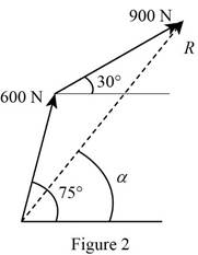
The length of the third side of the triangle formed gives the magnitude of the resultant force. The direction of the resultant force is specified by the angle the third side of the triangle makes with the horizontal.
Conclusion:
The length of the third side of the triangle is measured to be
Thus, the magnitude of the resultant force on the hook determined graphically using the triangle rule is
Want to see more full solutions like this?
Chapter 2 Solutions
Vector Mechanics for Engineers: Statics and Dynamics
Additional Engineering Textbook Solutions
Engineering Mechanics: Statics
Mechanics of Materials
Fluid Mechanics Fundamentals And Applications
Fundamentals of Aerodynamics
Fundamentals Of Thermodynamics
Introduction to Heat Transfer


- Two forces are applied as shown to a hook support. Knowing that the magnitude of P is 35 N, determine by trigonometry (a) the required angle a if the resultant R of the two forces applied to the support is to be horizontal, (b) the corresponding magnitude of R.arrow_forwardFour forces are applied at a joint of a structure. Determine the magnitude and direction of the resultant of concurrent forces.arrow_forwardKnowing that the tension in cable AC is 1260 N, determine (a) the angle between cable AC and the boom AB, (b) the projection on AB of the force exerted by cable AC at point A.arrow_forward
- Forces A, B and C are coplanar and act at a point. Force A is 12 kN at 90 degrees, B is 5 kN at 180 degrees and C is 13 kN at 293 degrees. Determine the resultant force.arrow_forwardTwo forces are applied as shown to a hook support. Knowing that the magnitude of P is 35 N, determine by trigonometry (a) the required angle α if the resultant R of the two forces applied to the support is to be horizontal, (b) the corresponding magnitude of R.arrow_forwardFind the magnitude and direction of the resultant of the two forces shown knowing that P=400 N and Q= 300 N. Fig. P2.92arrow_forward
- Three forces are acting on a bolt, namely, F, G, and H. If G is 324 N and H is 405 N, determine the following:a. the magnitude and direction of the components of force G when resolved along the u- and w-axes. b. the magnitude and direction of the resultant, denoted as P, of forces G and H c. the magnitude and direction of the minimum force F that will be added to P so that the resultant, R, is along the v-axisd. corresponding R *Note that the direction of force F in the figure is just assumed.arrow_forwardFor the hook support of Prob. 2.10, determine by trigonometry (a) the magnitude and direction of the smallest force P for which the resultant R of the two forces applied to the support is horizontal, (b) the corresponding magnitude of R.(Reference to Problem 2.10):Two forces are applied as shown to a hook support. Knowing that the magnitude of P is 35 N, determine by trigonometry (a) the required angle aif the resultant R of the two forces applied to the support is to be horizontal, (b) the corresponding magnitude of R.arrow_forwardKnowing that the tension in cable AC is 280 lb, determine (a) the angle between cable AC and the boom, (b) the projection on AB of the force exerted by cable AC at point A.arrow_forward
- Three forces are acting on a bolt, namely, F,G and H. If G and H have known values, determine (a) the magnitude and direction of the components of force G when resolved along the u and w axes (b) magnitude and direction of the resultant denoted as P, of forces G and H (c)the magnitude and direction of the minimum force F that will be added to P so that the resultant, R, is along the v-axis (d)corresponding R Note that the direction of F is only assumed.arrow_forwardA stake is being pulled out of the ground by means of two ropes as shown. Knowing that a= 30°, determine by trigonometry (a) the magnitude of the force P so that the resultant force exerted on the stake is vertical, (b) the corresponding magnitude of the resultant.arrow_forwardKnowing that the tension in cable AD is 180 lb, determine (a) the angle between cable AD and the boom AB, (b) the projection on AB of the force exerted by cable AD at point A.arrow_forward
 Elements Of ElectromagneticsMechanical EngineeringISBN:9780190698614Author:Sadiku, Matthew N. O.Publisher:Oxford University Press
 Mechanics of Materials (10th Edition)Mechanical EngineeringISBN:9780134319650Author:Russell C. HibbelerPublisher:PEARSON
 Thermodynamics: An Engineering ApproachMechanical EngineeringISBN:9781259822674Author:Yunus A. Cengel Dr., Michael A. BolesPublisher:McGraw-Hill Education
 Control Systems EngineeringMechanical EngineeringISBN:9781118170519Author:Norman S. NisePublisher:WILEY
 Mechanics of Materials (MindTap Course List)Mechanical EngineeringISBN:9781337093347Author:Barry J. Goodno, James M. GerePublisher:Cengage Learning
 Engineering Mechanics: StaticsMechanical EngineeringISBN:9781118807330Author:James L. Meriam, L. G. Kraige, J. N. BoltonPublisher:WILEY