
Videos
(a)
The resistors with maximum current.
Answer to Problem 5TP
Explanation of Solution
Given:
Parallel combination of two
Source voltage =
Calculations:
With the given information, following circuit diagram can be drawn:
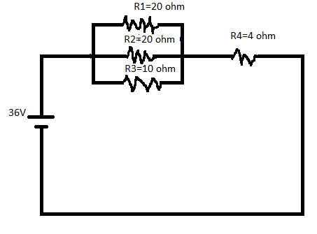
Here, the resistors
The resistor which provides the maximum current is
Conclusion:
Thus,
(b)
The resistor with maximum voltage drop.
Answer to Problem 5TP
Each of the resistor connected in parallel have the maximum voltage drop.
Explanation of Solution
Given:
Parallel combination of two
Source voltage =
Calculations:
With the given information, following circuit diagram can be drawn:
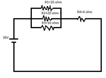
Here, the resistors
To find the voltage drop in the above circuit, compare the voltage across of
So, for finding the voltage drop, find the equivalent resistance separately as follows:
Conclusion:
Thus, the equivalent resistance of
(c)
The power dissipated in each of the resistor and total power dissipated in all resistor.
Answer to Problem 5TP
20 W in each
Output power source = 144 W.
Yes, they are equal as per law of conservation of energy.
Explanation of Solution
Given:
Parallel combination of two
Source voltage =
Calculations:
With the given information, following circuit diagram can be drawn:
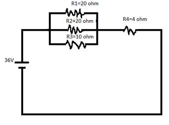
Here, the resistors
The voltage source is
To find the power dissipated in each of the resistor and the total power dissipated in each of the resistor, follow some steps one by one as below:
- Find the equivalent resistance and then find the total current.
- Voltage across parallel combination of resistance.
- Calculate the power dissipated in each resistor are:
- Total power dissipated in all the resistor.
- Find the total power output of the source as follows:
Conclusion:
The power dissipated of all the resistor and the total power output source are equal by the law of conservation of energy.
(e)
The values of all the resistors and the source voltage are doubled.
Answer to Problem 5TP
No effect.
Explanation of Solution
Given:
Parallel combination of two
Source voltage =
Calculations:
With the given information, following circuit diagram can be drawn:

Here, the resistors
If the values of all the resistors and the source voltage are doubled, then there would be no effect on the current.
Want to see more full solutions like this?
Chapter 21 Solutions
COLLEGE PHYSICS (OER)


- Consider a circuit that consists of a real battery with an emf and an internal resistance of r connected to a variable resistor R. (a) In order for the terminal voltage of the battery to be equal to the emf of the battery, what should the resistance of the variable resistor be adjusted to? (b) In older to get the maximum current from the battery, what should the resistance variable resistor be adjusted to? (c) In order for the maximum power output of the battery to be reached, what should the resistance of the variable resistor be set to?arrow_forwardA flashing lamp in a Christmas earring is based on an RC discharge of a capacitor through its resistance. The effective duration of the flash is 0.250 s, during which it produces an average 0.500 W from an average 3.00 V. (a) What energy does it dissipate? (b) How much charge moves through the lamp? (c) Find the capacitance, (d) What is the resistance of the lamp? (Since average values are given for some quantities, the shape of the pulse profile is not needed.)arrow_forwardIn this chapter, most examples and problems involved direct current (DC). DC circuits have the current flowing in one direction, from positive to negative. When the current was changing, it was changed linearly from I=ImaxtoI=+Imax and the voltage changed linearly from V=Vmax to V=+Vmax where Vmax=ImaxR .Suppose a voltage source is placed in series with a resistor of R = 10 that supplied a current that alternated as a sine wave, for example, I(t)=(3.00A)sin(24.00st) . (a) What would a graph of the voltage drop across the resistor V(t) versus time look like? (b) What would a plot of V(t) versus I(t) for one period look like? (Hint: If you are not sure, try plotting V(t) versus I(t) using a spreadsheet.)arrow_forward
- A 500- resistor, an uncharged 1.50-F capacitor and a 6.16-V emf are connected in series, (a) What is the initial current? (b) What is the RC time constant? (c) What is the current after one time constant? (d) What is the voltage on the capacitor after one time constant?arrow_forwardConsider a series RC circuit as in Figure P28.38 for which R = 1.00 M, C = 5.00 F, and = 30.0 V. Find (a) the time constant of the circuit and (b) the maximum charge on the capacitor after the switch is thrown closed. (c) Find the current in the resistor 10.0 s after the switch is closed.arrow_forwardA 1,00-?O voltmeter is placed in parallel with a 75.0kresistor in a circuit, (a) Draw a circuit diagram of the connection, (b) What is the resistance of the combination? If the voltage across the combination is kept the same as it was across the 75.0-kresistor alone, what is the percent increase in current? (d) If the current through the combination is kept the same as it was through the 75.0-kresistor alone, what is the percentage decrease in voltage? (e) Are the changes found in parts (c) and (d) significant? Discuss.arrow_forward
- Ralph has three resistors, R1, R2, and R3, connected in series. When connected to an ideal emf source E1, current I1 flows through the resistors. a. If the resistors are instead connected to a second source with E2=2E1, what is the new current through the resistors in terms of the first current? b. Show that, if each resistance is doubled and the resistors are connected in series to the second emf source, the current through the resistors is equal to I1.arrow_forwardConsider the circuit shown in Figure P28.21 on page 860. (a) Find the voltage across the 3.00-0 resistor, (b) Find the current in the 3.00-12 resistor.arrow_forwardA battery has an emf of 15.0 V. The terminal voltage of the battery is 11.6 V when it is delivering 20.0 W of power to an external load resistor R. (a) What is the value of R? (b) What is the internal resistance of the battery?arrow_forward
- A student makes a homemade resistor from a graphite pencil 5.00 cm long, where the graphite is 0.05 mm indiameter. The resistivity of the graphite is =1.38102/m . The homemade resistor is place inseries with a switch, a 10.00-mF capacitor and a 0.50-V power source, (a) What is the BC time constant of the circuit? (b) What is the potential drop across the pencil 1.00 s after the switch is closed?arrow_forwardConsider a series RC circuit as in Figure P18.35 for which R = 1.00 M, C = 5.00 F, and = 30.0 V. Find (a) the time constant of the circuit and (b) the maximum charge on the capacitor after the switch is thrown closed. (c) Find the current in the resistor 10.0 s after the switch is closed. Figure P18.35 Problem 35 and 38.arrow_forwardThe duration of a photographic flash is related to an RC time constant, which is 0.100F for a certain camera, (a) If the resistance of the flash lamp is 0.0400 duringdischarge, what is the size of the capacitor supplying its energy? (b) What is the time constant for charging the capacitor, if the charging resistance is 800 k ?arrow_forward

 Physics for Scientists and Engineers: Foundations...PhysicsISBN:9781133939146Author:Katz, Debora M.Publisher:Cengage Learning
 College PhysicsPhysicsISBN:9781938168000Author:Paul Peter Urone, Roger HinrichsPublisher:OpenStax College
 Physics for Scientists and Engineers, Technology ...PhysicsISBN:9781305116399Author:Raymond A. Serway, John W. JewettPublisher:Cengage Learning
 College PhysicsPhysicsISBN:9781285737027Author:Raymond A. Serway, Chris VuillePublisher:Cengage Learning
 College PhysicsPhysicsISBN:9781305952300Author:Raymond A. Serway, Chris VuillePublisher:Cengage Learning