Student Solutions Manual for Physics
3rd Edition
ISBN: 9780077340551
Author: GIAMBATTISTA, Alan; Richardson, Robert; Richardson, Betty
Publisher: McGraw-Hill Education
bartleby

Videos

Question
Book Icon
Chapter 21, Problem 93P

(a)

To determine

The reactance of the capacitor and the inductor.

(a)

Expert Solution
Check Mark

Answer to Problem 93P

The reactance of the capacitor is 20Ω and the reactance of the inductor is 35Ω.

Explanation of Solution

Write an expression for the capacitive reactance.

    XC=1ωC                                                                                                      (I)

Here, ω is the angular frequency, XC is the capacitive reactance and C is the capacitance.

Write an expression for the inductive reactance.

    XL=ωL                                                                                                    (II)

Here, XL is the inductive reactance and L is the inductance.

Conclusion:

Substitute 1.0×10³rad/s for ω and 50.0μF for C in equation (I) to find XC.

    XC=1(1.0×10³rad/s)(50.0μF)=1(1.0×103rad/s)((50.0μF)(106F1μF))=20Ω

Substitute 1.0×10³rad/s for ω and 35.0mH for L in equation (II) to find XL.

    XC=1(1.0×10³rad/s)(35.0mH)=1(1.0×103rad/s)((35.0mH)(103H1mH))=35Ω

Thus, the reactance of the capacitor is 20Ω and the reactance of the inductor is 35Ω.

(b)

To determine

The impedance.

(b)

Expert Solution
Check Mark

Answer to Problem 93P

The impedance is 25Ω.

Explanation of Solution

Write an expression for the impedance.

    Z=R2+(XLXC)2                                                                                     (III)

Here, Z is the impedance and R is the resistance.

Conclusion:

Substitute 20.0Ω for R, 35Ω for XL and 20Ω for XC in equation (III) to find Z.

    Z=(20.0Ω)2+(35Ω20Ω)2=(20.0Ω)2+(15Ω)2=25Ω

Thus, the impedance is 25Ω.

(c)

To determine

The rms current.

(c)

Expert Solution
Check Mark

Answer to Problem 93P

The rms current is 4.0A.

Explanation of Solution

Write an expression for the rms current.

    Irms=εrmsZ                                                                                      (IV)

Here, Irms is the rms current and εrms is the rms voltage.

Conclusion:

Substitute 100V for εrms and 25Ω for Z in equation (IV) to find Irms.

    Irms=100V25Ω=4.0A

Thus, the rms current is 4.0A.

(d)

To determine

The current amplitude.

(d)

Expert Solution
Check Mark

Answer to Problem 93P

The current amplitude is 5.7A.

Explanation of Solution

Write an expression for the current amplitude.

    I=2Irms                                                                                                 (V)

Here, I is the current amplitude.

Conclusion:

Substitute 4.0A for Irms in equation (V) to find I.

    I=2(4.0A)=5.7A

Thus, the current amplitude is 5.7A.

(e)

To determine

The phase angle.

(e)

Expert Solution
Check Mark

Answer to Problem 93P

The phase angle is 37°.

Explanation of Solution

Write an expression for the phase angle.

    cosϕ=RZϕ=cos1(RZ)                                                                                     (VI)

Here, ϕ is the phase angle.

Conclusion:

Substitute 20.0Ω for R and 25Ω for Z in equation (VI) to find ϕ.

    ϕ=cos1(20.0Ω25Ω)=cos1(0.8)=37°

Thus, the phase angle is 37°.

(f)

To determine

The rms voltage across each of the circuit elements.

(f)

Expert Solution
Check Mark

Answer to Problem 93P

The rms voltage across the resistance is 80V, the rms voltage across the inductor is 140V, and the rms voltage across the capacitor is 80V.

Explanation of Solution

Write an expression for the rms voltage across the resistance.

    VR,rms=IrmsR                                                                                     (VII)

Here, VR,rms is the rms voltage across the resistance.

Write an expression for the rms voltage across the inductor.

    VL,rms=IrmsXL                                                                                      (VIII)

Here, VL,rms is the rms voltage across the inductor.

Write an expression for the rms voltage across the capacitor.

    VC,rms=IrmsXC                                                                                     (IX)

Here, VC,rms is the rms voltage across the capacitor.

Conclusion:

Substitute 4.0A for Irms and 20.0Ω for R in equation (VII) to find VR,rms.

    VR,rms=(4.0A)(20.0Ω)=80V

Substitute 4.0A for Irms and 35Ω for XL in equation (VIII) to find VL,rms.

    VL,rms=(4.0A)(35Ω)=140V

Substitute 4.0A for Irms and 20Ω for XC in equation (IX) to find VC,rms.

    VC,rms=(4.0A)(20Ω)=80V

Thus, the rms voltage across the resistance is 80V, the rms voltage across the inductor is 140V, and the rms voltage across the capacitor is 80V.

(g)

To determine

If the current leads or lags the voltage.

(g)

Expert Solution
Check Mark

Answer to Problem 93P

The current lags the voltage.

Explanation of Solution

From the values of the capacitive reactance and inductive reactance, the inductive reactance is greater than the capacitive reactance.

    XL>XC

Conclusion:

As the dominant element is the inductor, the current lags the voltage.

Thus, the current lags the voltage.

(h)

To determine

Sketch the phasor diagram.

(h)

Expert Solution
Check Mark

Answer to Problem 93P

The phasor diagram is shown in figure 1.

Explanation of Solution

The voltages of the different circuit elements found in part (f) is used to draw the phasor diagram.

The rms voltage across the resistance VR is 80V.

The rms voltage across the inductor VL is 140V.

The rms voltage across the capacitor VC is 80V.

  VLVC=140V80V=60V

As the dominant element is the inductor, the current lags the voltage.

Conclusion:

The difference between the voltage across the inductor and the voltage across the capacitor is zero.

Sketch the phasor diagram.

Student Solutions Manual for Physics, Chapter 21, Problem 93P

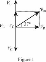
Thus, the phasor diagram is shown in figure 1.

Want to see more full solutions like this?

Subscribe now to access step-by-step solutions to millions of textbook problems written by subject matter experts!

Chapter 21 Solutions

Student Solutions Manual for Physics

Ch. 21 - Prob. 1CQCh. 21 - 2. Electric power is distributed long distances...Ch. 21 - 3. Explain the differences between average...Ch. 21 - Prob. 4CQCh. 21 - Prob. 5CQCh. 21 - Prob. 6CQCh. 21 - Prob. 7CQCh. 21 - Prob. 8CQCh. 21 - Prob. 9CQCh. 21 - Prob. 10CQCh. 21 - Prob. 11CQCh. 21 - Prob. 12CQCh. 21 - Prob. 13CQCh. 21 - Prob. 14CQCh. 21 - Prob. 15CQCh. 21 - Prob. 16CQCh. 21 - Prob. 17CQCh. 21 - 18. Let’s examine the crossover network of Fig....Ch. 21 - Prob. 1MCQCh. 21 - Prob. 2MCQCh. 21 - Prob. 3MCQCh. 21 - Prob. 4MCQCh. 21 - Prob. 5MCQCh. 21 - Prob. 6MCQCh. 21 - Prob. 7MCQCh. 21 - Prob. 8MCQCh. 21 - Prob. 9MCQCh. 21 - 10. Which graph is correct if the circuit...Ch. 21 - 1. A lightbulb is connected to a 120 V (rms), 60...Ch. 21 - 3. A 1500 w heater runs on 120 V rms. What is the...Ch. 21 - 4. A circuit breaker trips when the rms current...Ch. 21 - 5. A 1500 W electric hair dryer is designed to...Ch. 21 - 6. A 4.0 kW heater is designed to be connected to...Ch. 21 - 7. (a) What rms current is drawn by a 4200 w...Ch. 21 - 8. A television set draws an rms current of 2.50 A...Ch. 21 - 9. The instantaneous sinusoidal emf from an ac...Ch. 21 - 10. A hair dryer has a power rating of 1200 W at...Ch. 21 - Prob. 11PCh. 21 - 12. A variable capacitor with negligible...Ch. 21 - 13. At what frequency is the reactance of a 6.0...Ch. 21 - 14. A 0.400 μF capacitor is connected across the...Ch. 21 - 15. A 0.250 μF capacitor is connected to a 220 V...Ch. 21 - 16. A capacitor is connected across the terminals...Ch. 21 - 17. Show, from XC = l/(ωC), that the units of...Ch. 21 - 18. The charge on a capacitor in an ac circuit is...Ch. 21 - 19. A capacitor (capacitance = C) is connected to...Ch. 21 - 20. Three capacitors (2.0 μF, 3.0 μF, 6.0 μF) are...Ch. 21 - 21. A capacitor and a resistor are connected in...Ch. 21 - 22. A variable inductor with negligible resistance...Ch. 21 - Prob. 23PCh. 21 - Prob. 24PCh. 21 - 25. A solenoid with a radius of 8.0 × 10⁻³ m and...Ch. 21 - 26. A 4.00 mH inductor is connected to an ac...Ch. 21 - 27. Two ideal inductors (0.10 H, 0.50 H) are...Ch. 21 - Prob. 28PCh. 21 - 29. Suppose that an ideal capacitor and an ideal...Ch. 21 - 30. The voltage across an inductor and the...Ch. 21 - 31. Make a figure analogous to Fig. 21.5 for an...Ch. 21 - 32. A 25.0 mH inductor, with internal resistance...Ch. 21 - 33. An inductor has an impedance of 30.0 Ω and a...Ch. 21 - 34. A 6.20 mH inductor is one of the elements in...Ch. 21 - 35. A series combination of a resistor and a...Ch. 21 - 36. A 300.0 Ω resistor and a 2.5 μF capacitor are...Ch. 21 - Prob. 37PCh. 21 - 38. (a) Find the power factor for the RLC series...Ch. 21 - 39. A computer draws an rms current of 2.80 A at...Ch. 21 - 40. An RLC series circuit is connected to an ac...Ch. 21 - 41. An ac circuit has a single resistor,...Ch. 21 - 42. An RLC circuit has a resistance of 10.0 Ω,...Ch. 21 - 43. An ac circuit contains a 12.5 Ω resistor, a...Ch. 21 - 44. ✦ A 0.48 μF capacitor is connected in series...Ch. 21 - 45. A series combination of a 22.0 mH inductor...Ch. 21 - Prob. 46PCh. 21 - 47. A 150 Ω resistor is in series with a 0.75...Ch. 21 - 48. A series circuit with a resistor and a...Ch. 21 - 49. (a) What is the reactance of a 10.0 mH...Ch. 21 - Prob. 50PCh. 21 - Prob. 51PCh. 21 - Prob. 52PCh. 21 - Prob. 53PCh. 21 - Prob. 54PCh. 21 - 55. To test hearing at various frequencies, a...Ch. 21 - Prob. 56PCh. 21 - Prob. 57PCh. 21 - Prob. 58PCh. 21 - Prob. 59PCh. 21 - Prob. 60PCh. 21 - Prob. 61PCh. 21 - Prob. 62PCh. 21 - Prob. 63PCh. 21 - Prob. 64PCh. 21 - Prob. 65PCh. 21 - Prob. 66PCh. 21 - Prob. 67PCh. 21 - Prob. 68PCh. 21 - Prob. 69PCh. 21 - 70. The phasor diagram for a particular RLC series...Ch. 21 - Prob. 71PCh. 21 - Prob. 72PCh. 21 - Prob. 73PCh. 21 - Prob. 74PCh. 21 - Prob. 75PCh. 21 - Prob. 76PCh. 21 - Prob. 77PCh. 21 - Prob. 78PCh. 21 - Prob. 79PCh. 21 - Prob. 80PCh. 21 - Prob. 81PCh. 21 - Prob. 82PCh. 21 - Prob. 83PCh. 21 - Prob. 84PCh. 21 - 85. (a) When the resistance of an RLC series...Ch. 21 - Prob. 86PCh. 21 - Prob. 87PCh. 21 - Prob. 88PCh. 21 - Prob. 89PCh. 21 - Prob. 90PCh. 21 - Prob. 91PCh. 21 - Prob. 92PCh. 21 - Prob. 93PCh. 21 - Prob. 94PCh. 21 - Prob. 95PCh. 21 - Prob. 96PCh. 21 - Prob. 97PCh. 21 - Prob. 98PCh. 21 - Prob. 99PCh. 21 - Prob. 100PCh. 21 - Prob. 101P
Knowledge Booster
Background pattern image
Physics
Learn more about
Need a deep-dive on the concept behind this application? Look no further. Learn more about this topic, physics and related others by exploring similar questions and additional content below.
Recommended textbooks for you
Text book image
College Physics
Physics
ISBN:9781305952300
Author:Raymond A. Serway, Chris Vuille
Publisher:Cengage Learning
Text book image
University Physics (14th Edition)
Physics
ISBN:9780133969290
Author:Hugh D. Young, Roger A. Freedman
Publisher:PEARSON
Text book image
Introduction To Quantum Mechanics
Physics
ISBN:9781107189638
Author:Griffiths, David J., Schroeter, Darrell F.
Publisher:Cambridge University Press
Text book image
Physics for Scientists and Engineers
Physics
ISBN:9781337553278
Author:Raymond A. Serway, John W. Jewett
Publisher:Cengage Learning
Text book image
Lecture- Tutorials for Introductory Astronomy
Physics
ISBN:9780321820464
Author:Edward E. Prather, Tim P. Slater, Jeff P. Adams, Gina Brissenden
Publisher:Addison-Wesley
Text book image
College Physics: A Strategic Approach (4th Editio...
Physics
ISBN:9780134609034
Author:Randall D. Knight (Professor Emeritus), Brian Jones, Stuart Field
Publisher:PEARSON
Introduction To Alternating Current; Author: Tutorials Point (India) Ltd;https://www.youtube.com/watch?v=0m142qAZZpE;License: Standard YouTube License, CC-BY