
EBK FUNDAMENTALS OF ELECTRIC CIRCUITS
6th Edition
ISBN: 8220102801448
Author: Alexander
Publisher: YUZU
expand_more
expand_more
format_list_bulleted
Concept explainers
Videos
Textbook Question
Chapter 2.2, Problem 2PP
For the circuit shown in Fig. 2.9, calculate the voltage v, the conductance G, and the power p.
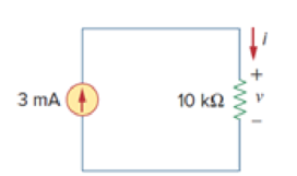
Figure 2.9
For Practice Prob. 2.2.
Expert Solution & Answer
Want to see the full answer?
Check out a sample textbook solution
Students have asked these similar questions
A 230-V, 1 000-c/s voltage is applied to a resistor in series
with C
capacıtance 0 06 µF, the reading is 100 V. Find the current
when the voltmeter is disconnected.
86
0 05 µF. When C is shunted by a voltmeter of
[0 0527 A.]
20 N
DC Circuit Is
500 N
40 V
75 N
Vs
100 N
For the DC circuit shown above, do the following (please show details of your calculations and indicate the proper units):
A. Compute the equivalent (total) resistance of the circuit.
B. According the Kirchoff's current law, write the equation that relates Is, Ij and l2.
C. Compute the current Is provided by the voltage source Vs.
D. Compute the voltage V1 across the 20 Ohms resistor.
E. Compute the voltage V2 across the 75 Ohms resistor.
F. Compute the current l2.
G. Compute the current I1.
H. Compute the voltage V3 across the 500 Ohms resistor.
1. Compute the voltage V4 across the 100 Ohms resistor.
J. Compute P1, the power dissipated by the 20 Ohms resistor.
K. Compute P2, the power dissipated by the 500 Ohms resistor.
L. Compute P3, the power dissipated by the 100 Ohms resistor.
M. Compute P4, the power dissipated by the 75 Ohms resistor.
N. Compute Ps, the power delivered by the voltage source.
O. Do you see any relationship between the…
1) A battery of emf V and internal resistance r is connected in series with an ammeter with resistance
TA and a resistor R. The current measured by the ammeter is I. a) Find the current through the circuit
if the resister R is doubled to 2R. Express your answer in terms of ra, A. r, and R. (b) What is the
maximum value of the ammeter resistance ra so that 90% of the power will be dissipated at the resister
R in the circuit for R-5.5 2 and V=7.5V, r-0.2 2?
Chapter 2 Solutions
EBK FUNDAMENTALS OF ELECTRIC CIRCUITS
Ch. 2.2 - The essential component of a toaster is an...Ch. 2.2 - For the circuit shown in Fig. 2.9, calculate the...Ch. 2.2 - A resistor absorbs an instantaneous power of 30...Ch. 2.3 - How many branches and nodes does the circuit in...Ch. 2.4 - Find v1 and v2 in the circuit of Fig. 2.22. Figure...Ch. 2.4 - Find vx and vo in the circuit of Fig. 2.24. Figure...Ch. 2.4 - Find vo and io in the circuit of Fig. 2.26. Figure...Ch. 2.4 - Find the current and voltages in the circuit shown...Ch. 2.6 - By combining the resistors in Fig.2.36, find Req....Ch. 2.6 - Find Rab for the circuit in Fig.2.39. Figure 2.39...
Ch. 2.6 - Calculate Geq in the circuit of Fig.2.41. Figure...Ch. 2.6 - Find v1 and v2 in the circuit shown in Fig. 2.43....Ch. 2.7 - Transform the wye network in Fig. 2.51 to a delta...Ch. 2.7 - For the bridge network in Fig. 2.54, find Rab and...Ch. 2.8 - Refer to Fig. 2.55 and assume there are six light...Ch. 2.8 - Following the ammeter setup of Fig. 2.61. design...Ch. 2 - The reciprocal of resistance is: (a) voltage (b)...Ch. 2 - Prob. 2RQCh. 2 - Prob. 3RQCh. 2 - The maximum current that a 2W, 80 k resistor can...Ch. 2 - Prob. 5RQCh. 2 - The current I in the circuit of Fig. 2.63 is: (a)...Ch. 2 - The current I0 of Fig. 2.64 is: (a) 4 A (b) 2 A...Ch. 2 - In the circuit in Fig. 2.65, V is: (a) 30 V (b) 14...Ch. 2 - Which of the circuit in Fig. 2.66 will give you...Ch. 2 - In the circuit of Fig. 2.67, a decrease in R3...Ch. 2 - Design a problem, complete with a solution, to...Ch. 2 - Find the hot resistance of a light bulb rated 60...Ch. 2 - A bar of silicon is 4 cm long with a circular...Ch. 2 - (a) Calculate current i in Fig. 2.68 when the...Ch. 2 - For the network graph in Fig. 2.69. find the...Ch. 2 - In the network graph shown in Fig. 2.70, determine...Ch. 2 - Determine the number of branches and nodes in the...Ch. 2 - Design a problem, complete with a solution, to...Ch. 2 - Find i1, i2, and i3 in Fig. 2.73. Figure 2.73 For...Ch. 2 - Determine i1 and i2 in the circuit of Fig. 2.74....Ch. 2 - In the circuit of Fig. 2.75, calculate V1 and V2....Ch. 2 - In the circuit in Fig. 2.76, obtain v1, v2, and...Ch. 2 - For the circuit in Fig. 2.77, use KCL to find the...Ch. 2 - Given the circuit in Fig. 2.78, use KVL to find...Ch. 2 - Calculate v and ix in the circuit of Fig. 2.79....Ch. 2 - Determine Vo in the circuit in Fig. 2.80. Figure...Ch. 2 - Obtain v1 through v3 in the circuit of Fig. 2.81....Ch. 2 - Find I and V in the circuit of Fig. 2.82. Figure...Ch. 2 - From the circuit in Fig. 2.83, find I, the power...Ch. 2 - Determine io in the circuit of Fig. 2.84. Figure...Ch. 2 - Find Vx in the circuit of Fig. 2.85. Figure 2.85...Ch. 2 - Find Vo in the circuit in Fig. 2.86 and the power...Ch. 2 - In the circuit shown in Fig. 2.87, determine Vx...Ch. 2 - For the circuit in Fig. 2.88, find Vo/Vs in terms...Ch. 2 - For the network in Fig. 2.89, find the current,...Ch. 2 - For the circuit in Fig. 2.90, io = 3 A. Calculate...Ch. 2 - Calculate Io in the circuit of Fig. 2.91. Figure...Ch. 2 - Design a problem, using Fig. 2.92, to help other...Ch. 2 - All resistors (R) in Fig. 2.93 are 10 each. Find...Ch. 2 - For the circuit in Fig. 2.95, determine i1 to i5....Ch. 2 - Find i1 through i4 in the circuit in Fig. 2.96....Ch. 2 - Obtain v and i in the circuit of Fig. 2.97. Figure...Ch. 2 - Using series/parallel resistance combination, find...Ch. 2 - Calculate Vo and Io in the circuit of Fig. 2.99....Ch. 2 - Find i and Vo in the circuit of Fig. 2.100. Figure...Ch. 2 - Given the circuit in Fig. 2.101 and that the...Ch. 2 - Find Req and io in the circuit of Fig. 2.102....Ch. 2 - Evaluate Req looking into each set of terminals...Ch. 2 - For the ladder network in Fig. 2.104, find I and...Ch. 2 - If Req = 50 in the circuit of Fig. 2.105, find R....Ch. 2 - Reduce each of the circuits in Fig. 2.106 to a...Ch. 2 - Calculate the equivalent resistance Rab at...Ch. 2 - For the circuits in Fig. 2.108, obtain the...Ch. 2 - Find the equivalent resistance at terminals a-b of...Ch. 2 - Find I in the circuit of Fig. 2.110. Figure 2.110Ch. 2 - Find the equivalent resistance Rab in the circuit...Ch. 2 - Convert the circuits in Fig. 2.112 from Y to ....Ch. 2 - Transform the circuits in Fig. 2.113 from to Y....Ch. 2 - Design a problem to help other students better...Ch. 2 - Obtain the equivalent resistance at the terminals...Ch. 2 - For the circuit shown in Fig. 2.116, find the...Ch. 2 - Obtain the equivalent resistance Rab in each of...Ch. 2 - Consider the circuit in Fig. 2.118. Find the...Ch. 2 - Calculate I0 in the circuit of Fig. 2.119. Figure...Ch. 2 - Determine V in the circuit of Fig. 2.120. Figure...Ch. 2 - Find Req and I in the circuit of Fig. 2.121....Ch. 2 - The 150 W tight bulb in Fig. 2.122 is rated at 110...Ch. 2 - If the three bulbs of Prob. 2.59 are connected in...Ch. 2 - As a design engineer, you are asked to design a...Ch. 2 - Prob. 62PCh. 2 - If an ammeter with an internal resistance of 100 ...Ch. 2 - The potentiometer (adjustable resistor) Rx in Fig....Ch. 2 - Design a circuit that uses a dArsonval meter (with...Ch. 2 - A 20-k/V voltmeter reads 10 V full scale. (a) What...Ch. 2 - (a) Obtain the voltage Vo in the circuit of Fig....Ch. 2 - (a) Find the current I in the circuit of Fig....Ch. 2 - A voltmeter used to measure Vo in the circuit in...Ch. 2 - (a) Consider the Wheatstone bridge shown in Fig....Ch. 2 - Figure 2.131 represents a model of a solar...Ch. 2 - Find Vo in the two-way power divider circuit in...Ch. 2 - An ammeter model consists of an ideal ammeter in...Ch. 2 - The circuit in Fig. 2.134 is to control the speed...Ch. 2 - Find Rab in the four-way power divider circuit in...Ch. 2 - Repeat Prob. 2.75 for the eight-way divider shown...Ch. 2 - Suppose your circuit laboratory has the following...Ch. 2 - In the circuit in Fig. 2.137, the wiper divides...Ch. 2 - Prob. 79CPCh. 2 - A loudspeaker is connected to an amplifier as...Ch. 2 - For a specific application, the circuit shown in...Ch. 2 - The pin diagram of a resistance array is shown in...Ch. 2 - Two delicate devices are rated as shown in Fig....
Knowledge Booster


Learn more about
Need a deep-dive on the concept behind this application? Look no further. Learn more about this topic, electrical-engineering and related others by exploring similar questions and additional content below.Similar questions
- Q2 (B) Note: If Multisim not available then then do it on paper. Verify Ohm’s Law using resistor of 1.5k Ohms on NI Multisim if the supplied voltages are:2V, 7V ,10V and 15V.Also plot the VI grapharrow_forwardDC Circuits 2.00 N 4. You are helping to design a simple circuit for an experiment. The circuit so far is shown to the right. + а. What is the equivalent resistance of the circuit? 3.00 0 1.00 N Please state this as an amount of Ohms to three significant digits. 4.00 N Req b. The experiment requires that the power dissipated by the 3.002 resistor be exactly 60.0W. Determine what the battery's voltage should be in order for this to happen. That is, determine the battery's voltage ɛ such that the 3.002 resistor losses energy at 60.0W. Please state this as a voltage to three significant figures. E =arrow_forwardFind the values of vs,v₁,and i2 in the figure below. 40 Q www www 2002. +51 2'|| | 20 Q 1₂ 5Q I + 4 Aarrow_forward
- It is electrical subject. Please show the complete and step by step solution.arrow_forwardFor the electric circuit in Figure Q2(b), compute Thevenin equivalent circuit with respect to the terminals a, b for the circuit shown. 12 N 72 V 20 N Figure Q2(b)arrow_forward2.39 Determine the power delivered by the dependent source in the circuit of Figure P2.39. ww 1592 0.51² ww 792 24 V Figure P2.39 www #502arrow_forward
- Please write the solution clearly so that I can understand it properlyarrow_forwardQ1. The open circuit voltage of a PV cell is 0.5V and the short circuit current is 2.4A. The fill factor for this cell is 0.7% and the current at maximum power point is 1.9A. a) Find voltage at maximum power point. b) Sketch the I-V and the P-V characteristics of the cell showing all the relevant values on the drawing.arrow_forwardIt is desired to obtain the Thevenin equivalent of a non-ideal battery. When no load is connected, the terminal voltage of the battery (that is, the voltage across nodes a and b) is measured to be 12.4 volts. When a 30-watt load is connected, the terminal voltage of the battery drops to 12 volts. a. What is the Thevenin voltage of the Thevenin equivalent for this battery? b. What is the Thevenin resistance of the Thevenin equivalent for this battery?c. A load is connected to source network. At the terminals of the source to which the load is connected, Vth=120 volts and Rth=10 ohms. What should be the resistance of the load so that it will draw the maximum power possible from the source network?arrow_forward
- 1. A battery of EMF 6 V has an internal resistance of 0.150. Calculate its terminal p.d. when delivering a current of 0.5 A. 2. State Ohm's Law. Use this law to find the value of a Resistance of an electric circuit which has a Voltage of 220 V and a current of 20Aarrow_forwardJust part d needed to solve ....arrow_forwardc. Research on the Kirchhoff's voltage law (KVL) and Kirchhoff's current law (KCL). Write those finding. d. Derive the KVL equation (VR1, Vr2, and Vr3) for circuit in Figure 1. e. Derive the KCL equation (I1, I2, and I3) for circuit in Figure 1. f. Derive the total resistance (RT) for circuit in Figure 1. g. Research on the mesh analysis and explain the concept of super mesh. Write those findings. h. Derive the mesh equations (VR1, Vr2, VR3 and Vr4) for circuit in Figure 2.arrow_forward
arrow_back_ios
SEE MORE QUESTIONS
arrow_forward_ios
Recommended textbooks for you
 Introductory Circuit Analysis (13th Edition)Electrical EngineeringISBN:9780133923605Author:Robert L. BoylestadPublisher:PEARSON
 Delmar's Standard Textbook Of ElectricityElectrical EngineeringISBN:9781337900348Author:Stephen L. HermanPublisher:Cengage Learning
 Programmable Logic ControllersElectrical EngineeringISBN:9780073373843Author:Frank D. PetruzellaPublisher:McGraw-Hill Education
 Fundamentals of Electric CircuitsElectrical EngineeringISBN:9780078028229Author:Charles K Alexander, Matthew SadikuPublisher:McGraw-Hill Education
 Electric Circuits. (11th Edition)Electrical EngineeringISBN:9780134746968Author:James W. Nilsson, Susan RiedelPublisher:PEARSON
 Engineering ElectromagneticsElectrical EngineeringISBN:9780078028151Author:Hayt, William H. (william Hart), Jr, BUCK, John A.Publisher:Mcgraw-hill Education,
Introductory Circuit Analysis (13th Edition)
Electrical Engineering
ISBN:9780133923605
Author:Robert L. Boylestad
Publisher:PEARSON
Delmar's Standard Textbook Of Electricity
Electrical Engineering
ISBN:9781337900348
Author:Stephen L. Herman
Publisher:Cengage Learning
Programmable Logic Controllers
Electrical Engineering
ISBN:9780073373843
Author:Frank D. Petruzella
Publisher:McGraw-Hill Education
Fundamentals of Electric Circuits
Electrical Engineering
ISBN:9780078028229
Author:Charles K Alexander, Matthew Sadiku
Publisher:McGraw-Hill Education
Electric Circuits. (11th Edition)
Electrical Engineering
ISBN:9780134746968
Author:James W. Nilsson, Susan Riedel
Publisher:PEARSON
Engineering Electromagnetics
Electrical Engineering
ISBN:9780078028151
Author:Hayt, William H. (william Hart), Jr, BUCK, John A.
Publisher:Mcgraw-hill Education,
Superposition Theorem; Author: The Organic Chemistry Tutor;https://www.youtube.com/watch?v=EX52BuZxpQM;License: Standard Youtube License