Videos
MCAT-Style Passage Problems
Lightbulb Failure
You’ve probably observed that the most common time for an incandescent lightbulb to fail is the moment when it is turned on. Let’s look at the properties of the bulb’s filament to see why this happens.
The current in the tungsten filament of a lightbulb heats the filament until it glows. The filament is so hot that some of the atoms on its surface fly off and end up sticking on a cooler part of the bulb. Thus the filament gets progressively thinner as the bulb ages. There will certainly be one spot on the filament that is a bit thinner than elsewhere. This thin segment will have a higher resistance than the surrounding filament. More power will be dissipated at this spot, so it won’t only be a thin spot, it also will be a hot spot.
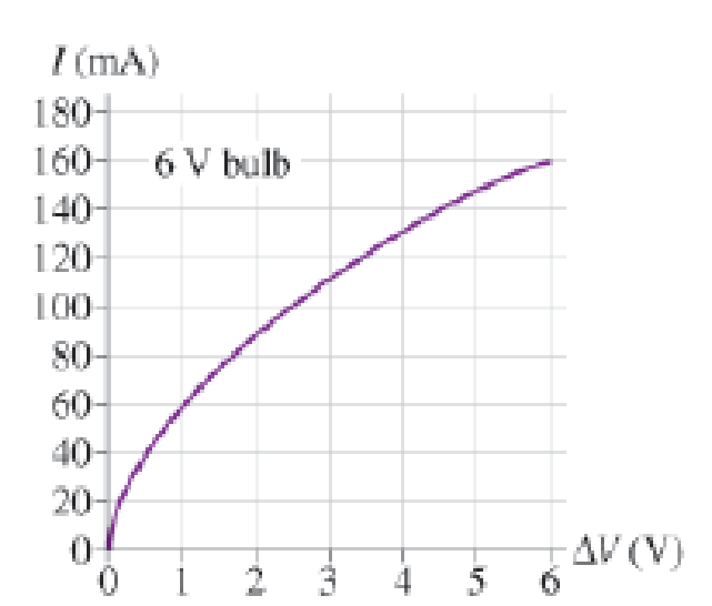
Now, let’s look at the resistance of the filament. The graph in Figure P22.70 shows data for the current in a lightbulb as a function of the potential difference across it. The graph is not linear, so the filament is not an ohmic material with a constant resistance. However, we can define the resistance at any particular potential difference ∆V to be R = ∆V/I. This ratio, and hence the resistance, increases with ∆V and thus with temperature.
Figure P22. 70
When the bulb is turned on, the filament is cold and its resistance is much lower than during normal, high-temperature operation. The low resistance causes a surge of higher-than-normal current lasting a fraction of a second until the filament heats up. Because power dissipation is I2R, the power dissipated during this first fraction of a second is much larger than the bulb’s rated power. This current surge concentrates the power dissipation at the high-resistance thin spot, perhaps melting it and breaking the filament.
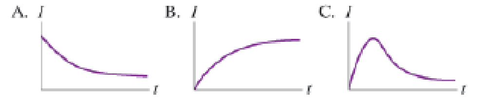
Which of the curves in Figure P22.72 best represents the expected variation in current as a function of time in the short time interval immediately after the bulb is turned on?
Figure P22.72
Want to see the full answer?
Check out a sample textbook solution
Chapter 22 Solutions
College Physics: A Strategic Approach Technology Update, Books a la Carte Plus Mastering Physics with Pearson eText -- Access Card Package (3rd Edition)
Additional Science Textbook Solutions
University Physics with Modern Physics (14th Edition)
An Introduction to Thermal Physics
Physics for Scientists and Engineers: A Strategic Approach with Modern Physics (4th Edition)
Conceptual Physical Science (6th Edition)
Tutorials in Introductory Physics


- Ralph has three resistors, R1, R2, and R3, connected in series. When connected to an ideal emf source E1, current I1 flows through the resistors. a. If the resistors are instead connected to a second source with E2=2E1, what is the new current through the resistors in terms of the first current? b. Show that, if each resistance is doubled and the resistors are connected in series to the second emf source, the current through the resistors is equal to I1.arrow_forwardFour resistors are connected to a battery as shown in Figure P21.40. The current in the battery is I, the battery emf is , and the resistor values are R1 = R, R2 = 2R, R3 = 4R, and R4 = 3R. (a) Rank the resistors according to the potential difference across them, from largest to smallest. Note any cases of equal potential differences. (b) Determine the potential difference across each resistor in terms of . (c) Rank the resistors according to the current in them, from largest to smallest. Note any cases of equal currents. (d) Determine the current in each resistor in terms of I. (e) If R3 is increased, what happens to the current in each of the resistors? (f) In the limit that R3 , what are the new values of the current in each resistor in terms of I, the original current in the battery? Figure P21.40arrow_forwardA 20.00-V battery is used to supply current to a 10-k resistor. Assume the voltage drop across any wires used for connections is negligible, (a) What is the current through the resistor? (b) What is the power dissipated by the resistor? (c) What is the power input from the battery; assuming all the electrical power is dissipated by the resistor? (d) What happens to the energy dissipated by the resistor?arrow_forward
- Figure 6 below shows an RC- circuit where the capacitor Is initially uncharged. 100n 502 12 V 1502 10 HF V. Figure 6 a) What is the current through the battery immediately after the switch S is closed? b) What is the current through the battery long time after the switch S is closed?arrow_forwardProblem 7: Why do lights dim when a large appliance is switched on? The answer is that the large current the appliance motor draws causes a significant potential drop in the wires and reduces the voltage across the lights. This is called an IR drop because it is simply due to the current and resistance of the device in question. Refrigerator Low P, Bulb dims R,= wire resistance Low R, large /, Motor Part (a) Assume the bulb in question dissipates P2 = 75 W when connected to the 120 V AC source. What average power will the bulb dissipate if I = 13.5 A passes through the wires when the motor comes on? Assume a negligible change in bulb resistance, while the resistance of the wires are R1 = 0.55 Q. Numeric : A numeric value is expected and not an expression. P2' = Part (b) How much power, P3, in watts, is consumed on average by the motor? Numeric : A numeric value is expected and not an expression. P3 =arrow_forwardQU5 a). A circuit consist of five resistors connected as below, determine the effective resistance in the circuit. R3 R5 R2 R4 Given that R1, R2,R3,R4 and R are given respectively as 500, 250, 300, 600 and 700Q, what is the current in the circuit if the potential across the resistors is 24 V?arrow_forward
- Circuit in phone charger. Resistor can only dissipate up to 0.30 Watts of power before melting. When charger is operating normally, resistor typically has voltage of 4.2 V across, and dissipates only 0.10 Watts of power. a) What is the resistance of this resistor? b) How much current does it normally carry? c) What is the max voltage you can put across it before it overheats and melts?arrow_forwardI'm trying to understand this figure Assume the capacitor in the circuit is initially uncharged. Can you calculate the current through each resistor right after the circuit is connected? If so, can you explain and show how you did it? What if the circuit has been connected and left alone for a long time. Calculate the charge on the capacitor platearrow_forwardA 10 Ω resistor and a 20 Ω resistor are connected in parallel with a power supply. If the power dissipated by the 10 Ω resistor is 100 W, the power dissipated by 20 Ω resistor is Blank 1 Watts. what is the wattsarrow_forward
- R1 R2 R3 RA 1. In the figure above, let R1 = 10 2, R2 = R3 = 5N, and R4 = 82 respectively with a battery whose emf is E = 9 V. Find the current and potential drop across each resistor. Assume that current is going in clockwise direction.arrow_forwardU03arrow_forwardIn the circuit, R = 17 kQ2, C = 0.3 μF, and V = 45 V. The capacitor is allowed to charge fully and then the switch is changed from position a to position b. a) What is the time constant? b) What is the current in the resistor 7.7 ms later? c) What is the voltage across the resistor 7.7 ms later? V a b R www To continue, please enter the result of c) in units of V. Round your answer to 1 decimal place.arrow_forward
 Principles of Physics: A Calculus-Based TextPhysicsISBN:9781133104261Author:Raymond A. Serway, John W. JewettPublisher:Cengage Learning
 Physics for Scientists and Engineers: Foundations...PhysicsISBN:9781133939146Author:Katz, Debora M.Publisher:Cengage Learning
 Physics for Scientists and Engineers, Technology ...PhysicsISBN:9781305116399Author:Raymond A. Serway, John W. JewettPublisher:Cengage Learning