
Concept explainers
Videos
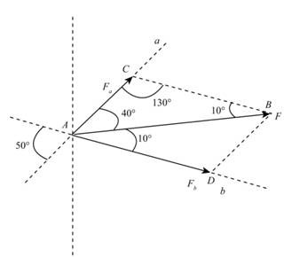
A sheet of an experimental composite is subjected to a simple tension test to determine its strength along a particular direction. The composite is reinforced by the Kevlar fibers shown, and a close-up showing the direction of the applied tension force F in relation to the fiber directions at point A is shown. If the magnitude of F is 2.5 kN, determine the components
Want to see the full answer?
Check out a sample textbook solution
Chapter 2 Solutions
Engineering Mechanics: Statics
Additional Engineering Textbook Solutions
Introduction to Heat Transfer
Thinking Like an Engineer: An Active Learning Approach (3rd Edition)
Automotive Technology: Principles, Diagnosis, and Service (5th Edition)
Fundamentals of Heat and Mass Transfer
Statics and Mechanics of Materials (5th Edition)
Introduction To Finite Element Analysis And Design


- 3. Calculate the tension in each of the three ropes which support the uniform steel plate weighing 7.72 N/mm^3arrow_forwardThe 7m by 9m building slab is subjected to 4 parallel loads. Determine the force F equivalent to this 4 force system, and its point of application.arrow_forwardFor the following structure, determine the internal forces at the midpoint between B and C. Angle ? is equal to 60°.arrow_forward
- Determine all the components of the force applied on bolt A and the angles characterizing the force's direction if the bolt supports a tower via wire with a tension of 2500 N.arrow_forward1. The flagpole is supported by three cables as shown such that the cables keep the flagpole upright.a. Draw an ideally constructed force diagram of point A, the point on the flagpole connected to the cables?b. What is the unit vector that defines the direction of the tension on cable AC acting on A?c. If the magnitude of force AB is 100 N, what is the component along the y-axis? d. What best approximates the force on cable AC? e. What is the resultant of the forces of the three cables acting at point A?arrow_forwardThe cable carrying 60-lb loads at B and C is held in the position shown by the horizontal force P = 80 lb applied at A. Determine the following: Determine the force in segment BC. Determine the force in segment CD. Determine the value of h. Determine the smallest measure of angle ?BCx segment BC makes with the horizontal. Determine the smallest measure of angle ?CDx segment CD makes with the horizontal.arrow_forward
- The truss shown is composed of 45° right triangles. The crossed members in the center two panels are slender tie rods incapable of supporting compression. Find the forces in all four cross members. The forces are positive if in tension and zero if they attempt to go into compression. Also find the force in member MN (positive if in tension, negative if in compression).arrow_forwardDetermine the distance from G of the resultant force for the truss shown below,if the load at B is increased by 6.arrow_forwardCable ABC of length 5 m supports the force W at B. Determine (a) the angles 1 and 2; and (b) the force in each cable segment in terms of W.arrow_forward
- Cable AB supports the uniformly distributed load of 4 kN/m. If the slope of the cable at A is zero, compute (a) the maximum tensile force in the cable; and (b) the length of the cable.arrow_forwardFor the cable ABCD determine (a) the angles 2 and 3; (b) the force in each segment; and (c) the span L and the raise H.arrow_forwardThe structure is supported by a pin at C and a cable attached to A. The cable runs over the small pulley D. Find the internal force systems acting on sections 1 and 2.arrow_forward
 International Edition---engineering Mechanics: St...Mechanical EngineeringISBN:9781305501607Author:Andrew Pytel And Jaan KiusalaasPublisher:CENGAGE L