
Videos
A real battery is not just an emf. We can If model a real 1.5 V battery as a 1.5 V emf in series with a resistor known as the “internal resistance,” as shown in Figure P23.55. A typical battery has 1.0 Ω internal resistance due to imperfections that limit current through the battery. When there’s no current through the battery, and thus no voltage drop across the internal resistance, the potential difference between its terminals is 1.5 V. the value of the emf. Suppose the terminals of this battery are connected to a 2.0 Ω resistor.
Figure P23.55
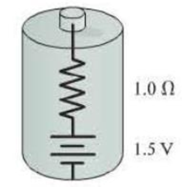
- a. What is the potential difference between the terminals of the battery?
- b. What fraction of the battery’s power is dissipated by the internal resistance?

Trending nowThis is a popular solution!

Chapter 23 Solutions
Mastering Physics with Pearson eText -- Standalone Access Card -- for College Physics: A Strategic Approach (4th Edition)
Additional Science Textbook Solutions
University Physics Volume 1
The Cosmic Perspective Fundamentals (2nd Edition)
Tutorials in Introductory Physics
Essential University Physics: Volume 2 (3rd Edition)
Physics: Principles with Applications
University Physics (14th Edition)


- In Figure P29.81, N real batteries, each with an emf and internal resistance r, are connected in a closed ring. A resistor R can be connected across any two points of this ring, causing there to be n real batteries in one branch and N n resistors in the other branch. Find an expression for the current through the resistor R in this case.arrow_forwardA battery is used to charge a capacitor through a resistor as shown in Figure P27.44. Show that half the energy supplied by the battery appears as internal energy in the resistor and half is stored in the capacitor. Figure P27.44arrow_forwardIf the terminals of a battery with zero internal resistance are connected across two identical resistors in series, the total power delivered by the battery is 8.00 W. If the same battery is connected across the same resistors in parallel, what is the total power delivered by the battery? (a) 16.0 W (b) 32.0 W (c) 2.00 W (d) 4.00 W (e) none of those answersarrow_forward
- What is the equivalent resistance between points a and b of the six resistors shown in Figure P29.70? FIGURE P29.70arrow_forwardA resistor R1 = 10 Ω is connected in parallel with a second resistor R2 = 4R1. This parallel configuration is then connected in series with R3 = R1/5 and across a cell with voltage V = 18 V. What is the current flowing through resistor R3? Select one: a. 1.25 A b. 4.0 A c. 1.8 A d. 360 mAarrow_forwardWhen charging a capacitor in series with a resistor, using a 10 V emf source, what would you expect the voltage of the capacitor to be at an initial time of t = τ ? a. 3.68 V b. 0.368 V c. 6.32 V d. 10 V e. 0.632 Varrow_forward
- A capacitor, initially at 21 V, is discharged using an 19 Ω resistor. After 155 s there are 4.2 V across the capacitor. What is the capacitance of the capacitor? (in F) a. 36.6 F b. 13.1 F c. 8.16 F d. 5.07 Farrow_forward(a) Given a 52.0 V battery and 20.0 Ω and 84.0 Ω resistors, find the current (in A) and power (in W) for each when connected in series. I20.0 Ω= A P20.0 Ω= W I84.0 Ω= A P84.0 Ω= W (b)Repeat when the resistances are in parallel. I20.0 Ω= A P20.0 Ω= W I84.0 Ω= A P84.0 Ω= Warrow_forwardThe circuit in the drawing shows two resistors, a C = 7.0 μF capacitor, and a V = 10 V battery. When the capacitor is fully charged, what is the magnitude (q) of the charge on one of its plates?arrow_forward
- (a) Find the voltage drop (in V) in an extension cord having a 0.0650 Ω resistance and through which 5.45 A is flowing. V (b) A cheaper cord utilizes thinner wire and has a resistance of 0.340 Ω. What is the voltage drop (in V) in it when 5.45 A flows?V (c)Why is the voltage to whatever appliance is being used reduced by this amount? What is the effect on the appliance?arrow_forwardThe figure displays two circuits with a charged capacitor that is to be discharged through a resistor when a switch is closed. In figure (a) below, R1 = 21.9 Ω and C1 = 5.26 μF. In figure (b) below, R2 = 10.9 Ω and C2 = 8.08 μF. The ratio of the initial charges on the two capacitors is q02/q01 = 1.64. At time t = 0, both switches are closed. At what time t do the two capacitors have the same charge?arrow_forwarda. What is the current in each resistor? I1___ I2____ I3____ I4_____ b. What is the voltage across each resistor ? c. What power does the battery deliver to the circuit? pbattery____ d. What is the current in each resistor when the switchh is open? I1_____ I2_____ I3______ I4_______ e. What is the voltage across each resistor when the switch is open? V1____ V2_____ V3_____ V4_______ f. Calculate the power delivered by the battery? Explain why the power delivered by the battery increases or decreases when the switch was opened?arrow_forward
 Principles of Physics: A Calculus-Based TextPhysicsISBN:9781133104261Author:Raymond A. Serway, John W. JewettPublisher:Cengage Learning
 Physics for Scientists and Engineers: Foundations...PhysicsISBN:9781133939146Author:Katz, Debora M.Publisher:Cengage Learning
 Physics for Scientists and EngineersPhysicsISBN:9781337553278Author:Raymond A. Serway, John W. JewettPublisher:Cengage Learning
 Physics for Scientists and Engineers with Modern ...PhysicsISBN:9781337553292Author:Raymond A. Serway, John W. JewettPublisher:Cengage Learning