Student's Solutions Manual for College Physics: A Strategic Approach Volume 2 (Chs. 17-30)
3rd Edition
ISBN: 9780321908858
Author: Knight (Professor Emeritus), Randall D.; Jones, Brian; Field, Stuart
Publisher: PEARSON
expand_more
expand_more
format_list_bulleted
Videos
Textbook Question
Chapter 23, Problem 7P
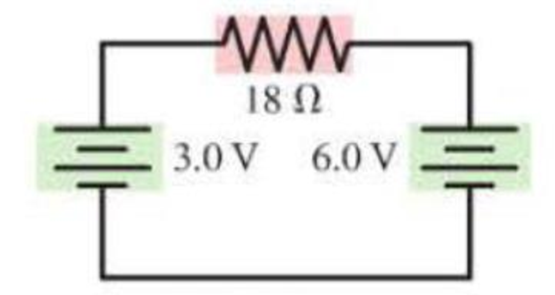
a. What are the magnitude and direction of the current in the 18 Ω resistor in Figure P23.7?
b. Draw a graph of the potential as a function of the distance traveled through the circuit, traveling clockwise from V= 0 V at the lower left comer. See Figure P23.9 for an example of such a graph.
Figure P23.7
Expert Solution & Answer
Want to see the full answer?
Check out a sample textbook solution
Chapter 23 Solutions
Student's Solutions Manual for College Physics: A Strategic Approach Volume 2 (Chs. 17-30)
Ch. 23 - The tip of a flashlight bulb is touching the top...Ch. 23 - A flashlight bulb is connected to a battery and is...Ch. 23 - Current Iin flows into three resistors connected...Ch. 23 - The circuit in Figure Q23.4 has two resistors,...Ch. 23 - The circuit in Figure Q23.5 has a battery and two...Ch. 23 - In the circuit shown in Figure Q23.6, bulbs A and...Ch. 23 - Figure Q23.7 shows two circuits. The two batteries...Ch. 23 - Figure Q23.8 shows two circuits. The two batteries...Ch. 23 - a. In Figure Q23.9, what fraction of current I...Ch. 23 - Two of the three resistors in Figure Q23.10 are...
Ch. 23 - Two of the three resistors in Figure Q23.11 are...Ch. 23 - Rank in order, from largest to smallest, the...Ch. 23 - The three bulbs in Figure Q23.13 are identical....Ch. 23 - The four bulbs in Figure Q23.14 are identical....Ch. 23 - Figure Q23.15 shows five identical bulbs connected...Ch. 23 - a. The three bulbs in Figure Q23.16 are identical....Ch. 23 - Initially, bulbs A and B in Figure Q23.17 are both...Ch. 23 - a. Consider the points a and b in Figure Q23.18....Ch. 23 - When the switch in Figure Q23.19 is closed, a....Ch. 23 - A voltmeter is (incorrectly) inserted into a...Ch. 23 - An ammeter is (incorrectly) inserted into a...Ch. 23 - Rank in order, from largest to smallest, the...Ch. 23 - Figure Q23.23 shows a circuit consisting of a...Ch. 23 - Figure Q23.24 shows the volt age as a function of...Ch. 23 - A charged capacitor could be connected to two...Ch. 23 - A flashing light is controlled by the charging and...Ch. 23 - A device to make an electrical measurement of skin...Ch. 23 - Consider the model of nerve conduction in...Ch. 23 - Adding a myelin sheath to an axon results in...Ch. 23 - What is the current in the circuit of Figure...Ch. 23 - Which resistor in Figure Q23.30 dissipates the...Ch. 23 - Normally, household lightbulbs are connected in...Ch. 23 - A metal wire of resistance R is cut into two...Ch. 23 - What is the value of resistor R in Figure Q23.34?...Ch. 23 - Two capacitors are connected in series. They are...Ch. 23 - If a cells membrane thickness doubles but the cell...Ch. 23 - If a cells diameter is reduced by 50% without...Ch. 23 - Draw a circuit diagram tor the circuit of Figure...Ch. 23 - Draw a circuit diagram for the circuit of Figure...Ch. 23 - Draw a circuit diagram for the circuit of Figure...Ch. 23 - In Figure P23.4, what is the current in the wire...Ch. 23 - The lightbulb in the circuit diagram of Figure...Ch. 23 - a. What are the magnitude and direction of the...Ch. 23 - a. What are the magnitude and direction of the...Ch. 23 - a. What is the potential difference across each...Ch. 23 - The current in a circuit with only one battery is...Ch. 23 - What is the equivalent resistance of each group of...Ch. 23 - What is the equivalent resistance of each group of...Ch. 23 - Prob. 12PCh. 23 - Prob. 13PCh. 23 - You have a collection of 1.0 k resistors. How can...Ch. 23 - You have a collection of six 1.0 k resistors. What...Ch. 23 - You have six 1.0 k resistors. How can you connect...Ch. 23 - What is the equivalent resistance between points a...Ch. 23 - What is the equivalent resistance between points a...Ch. 23 - The currents in two resistors in a circuit are...Ch. 23 - Two batteries supply current to the circuit in...Ch. 23 - Part of a circuit is shown in Figure P23.21. a....Ch. 23 - What is the value of resistor R in Figure P23.22?...Ch. 23 - What are the resistances R and the emf of the...Ch. 23 - The ammeter in Figure P23.24 reads 3.0 A. Find I1,...Ch. 23 - Find the current through and the potential...Ch. 23 - Find the current through and the potential...Ch. 23 - For the circuit shown in Figure P23.27, find the...Ch. 23 - Consider the potential differences between pairs...Ch. 23 - For the circuit shown in Figure P23.29, find the...Ch. 23 - A photoresistor, whose resistance decreases with...Ch. 23 - The two unknown resistors in Figure P23.31 have...Ch. 23 - A 6.0 F capacitor, a 10 F capacitor, and a 16 F...Ch. 23 - A 6.0 F capacitor, a 10 F capacitor, and a 16 F...Ch. 23 - You need a capacitance of 50 F, but you dont...Ch. 23 - You need a capacitance of 50 F, but you dont...Ch. 23 - What is the equivalent capacitance of the three...Ch. 23 - What is the equivalent capacitance of the three...Ch. 23 - For the circuit of Figure P23.38, a. What is the...Ch. 23 - For the circuit of Figure P23.39. a. What is the...Ch. 23 - What is the time constant for the discharge of the...Ch. 23 - What is the time constant for the discharge of the...Ch. 23 - After how many time constants has the voltage...Ch. 23 - A 10F capacitor initially charged to 20C is...Ch. 23 - A capacitor charging circuit consists of a...Ch. 23 - The switch in Figure P23.45 has been in position a...Ch. 23 - A 9.0-nm-thick cell membrane undergoes an action...Ch. 23 - A cell membrane has a resistance and a capacitance...Ch. 23 - Changing the thickness of the myelin sheath...Ch. 23 - A particular myelinated axon has nodes spaced 0.80...Ch. 23 - To measure signal propagation in a nerve in the...Ch. 23 - A myelinated axon conducts nerve impulses at a...Ch. 23 - How much power is dissipated by each resistor in...Ch. 23 - Two 75 W (120 V) lightbulbs are wired in series,...Ch. 23 - The corroded contacts in a lightbulb socket have...Ch. 23 - A real battery is not just an emf. We can If model...Ch. 23 - For the real battery shown in Figure P23.55,...Ch. 23 - Batteries are recharged by connecting them to a...Ch. 23 - When two resistors are connected in parallel...Ch. 23 - The 10 resistor in Figure P23.59 is dissipating 40...Ch. 23 - At this instant the current in the circuit of...Ch. 23 - What is the equivalent resistance between points a...Ch. 23 - What is the current through the battery in Figure...Ch. 23 - What is the ratio P parallel/P series of the total...Ch. 23 - You have a device that needs a voltage reference...Ch. 23 - There is a current of 0.25 A in the circuit of...Ch. 23 - A circuit youre building needs an ammeter that...Ch. 23 - A circuit youre building needs a voltmeter that...Ch. 23 - For the circuit shown in Figure P23.68, find the...Ch. 23 - You have three 12 F capacitors. Draw diagrams...Ch. 23 - Initially, the switch in Figure P23.70 is in...Ch. 23 - The capacitor in an RC circuit with a time...Ch. 23 - The capacitor in Figure P23.72 is initially...Ch. 23 - What value resistor will discharge a 1.0 F...Ch. 23 - The charging circuit for the flash system of a...Ch. 23 - A capacitor is discharged through a 100 resistor....Ch. 23 - A 50 /F capacitor that had been charged to 30 V is...Ch. 23 - The switch in Figure P23.77 has been closed for a...Ch. 23 - Intermittent windshield wipers use a variable...Ch. 23 - In Example 23.14 we estimated the capacitance of...Ch. 23 - The giant axon of a squid is 0.5 mm in diameter,...Ch. 23 - A cell has a 7.0-nm-thick membrane with a total...Ch. 23 - The Defibrillator A defibrillator is designed to...Ch. 23 - The Defibrillator A defibrillator is designed to...Ch. 23 - The Defibrillator A defibrillator is designed to...Ch. 23 - A defibrillator is designed to pass a large...Ch. 23 - The voltage produced by a single nerve or muscle...Ch. 23 - The voltage produced by a single nerve or muscle...Ch. 23 - The voltage produced by a single nerve or muscle...Ch. 23 - The voltage produced by a single nerve or muscle...
Additional Science Textbook Solutions
Find more solutions based on key concepts
Express the unit vectors in terms of (that is, derive Eq. 1.64). Check your answers several ways Also work o...
Introduction to Electrodynamics
Explain all answer clearly, with complete sentences and proper essay structure if needed. An asterisk (*) desig...
Cosmic Perspective Fundamentals
3. What is free-fall, and why does it make you weightless? Briefly describe why astronauts are weightless in th...
The Cosmic Perspective
Concentric conducting spherical shells carry charges Q and -Q, respectively. The inner shell has negligible thi...
University Physics Volume 2
5. A 65 kg gymnast wedges himself between two closely spaced vertical walls by pressing his hands and feet ag...
Physics for Scientists and Engineers: A Strategic Approach with Modern Physics (4th Edition)
Suppose the distance between two objects is cut in half. Is the gravitational force between them (a) quartered,...
Essential University Physics: Volume 1 (3rd Edition)
Knowledge Booster


Learn more about
Need a deep-dive on the concept behind this application? Look no further. Learn more about this topic, physics and related others by exploring similar questions and additional content below.Similar questions
- (a) What is the average power output of a heart defibrillator that dissipates 400 J of energy in 10.0 ms? (b) Considering the high-power output, why doesn’t the defibrillator produce serious bums?arrow_forwardThe circuit shown in Figure P28.78 is set up in the laboratory to measure an unknown capacitance C in series with a resistance R = 10.0 M powered by a battery whose emf is 6.19 V. The data given in the table are the measured voltages across the capacitor as a function of lime, where t = 0 represents the instant at which the switch is thrown to position b. (a) Construct a graph of In (/v) versus I and perform a linear least-squares fit to the data, (b) From the slope of your graph, obtain a value for the time constant of the circuit and a value for the capacitance. v(V) t(s) In (/v) 6.19 0 5.56 4.87 4.93 11.1 4.34 19.4 3.72 30.8 3.09 46.6 2.47 67.3 1.83 102.2arrow_forwardIn Figure P29.81, N real batteries, each with an emf and internal resistance r, are connected in a closed ring. A resistor R can be connected across any two points of this ring, causing there to be n real batteries in one branch and N n resistors in the other branch. Find an expression for the current through the resistor R in this case.arrow_forward
- The circuit in Figure P21.59 has been connected for a long time. (a) What is the potential difference across the capacitor? (b) If the battery is disconnected from the circuit, over what time interval does the capacitor discharge to one-tenth its initial voltage?arrow_forwardFigure P18.37 shows a simplified model of a cardiac defibrillator, a device used to patients in ventricular fibrillation. When the switch S is toggled to the left, the capacitor C charges through the resistor R .When the switch is toggled to the right, the capacitor discharges current through the patients torso, modeled as the resistor Rtorso, allowing the hearts normal rhythm to be reestablished. (a) If the capacitor is initially uncharged with C = 8.00 F and = 1250 V, find the value of R required to charge the capacitor to a voltage of 775 V in 1.50 s. (b) If the capacitor is then discharged across the patients torso with, Rtorso = 1250 , calculate the voltage across the capacitor after 5.00 ms. Figure P18.37arrow_forwardAt one instant, a current of 6.0 A flows through part of a circuit as shown in Figure P33.12. Determine the instantaneous potential difference between points A and B if the current starts to decrease at a constant rate of 1.0 102 A/s. FIGURE P33.12arrow_forward
- Figure P29.60 shows a simple RC circuit with a 2.50-F capacitor, a 3.50-M resistor, a 9.00-V emf, and a switch. What are a. the charge on the capacitor, b. the current in the resistor, c. the rate at which the capacitor is storing energy, and d. the rate at which the battery is delivering energy exactly 7.50 s alter the switch is closed?arrow_forwardIn the circuit of Figure P27.25, the switch S has been open for a long time. It is then suddenly closed. Take = 10.0 V, R1 = 50.0 k, R2 = 100 k, and C = 10.0 F. Determine the time constant (a) before the switch is closed and (b) after the switch is closed. (c) Let the switch be closed at t = 0. Determine the current in the switch as a function of time. Figure P27.25 Problems 25 and 26.arrow_forwardThree resistors with resistances R1 = R/2 and R2 = R3 = R are connected as shown, and a potential difference of 225 V is applied across terminals a and b (Fig. P29.49). a. If the resistor R1 dissipates 75.0 W of power, what is the value of R? b. What is the total power supplied to the circuit by the emf? c. What is the potential difference across each of the three resistors?arrow_forward
- In the circuit of Figure P27.25, the switch S has been open for a long time. It is then suddenly closed. Determine the time constant (a) before the switch is closed and (b) after the switch is closed. (c) Let the switch be closed at t = 0. Determine the current in the switch as a function of time. Figure P27.25 Problems 25 and 26.arrow_forwardFigure P29.41 shows three resistors (R1 = 14.0 , R2 = 8.00 , and R3 = 10.0 ) and two batteries connected in a circuit. a. What is the current in each of the resistors? b. How much power is delivered to each of the resistors?arrow_forward
arrow_back_ios
arrow_forward_ios
Recommended textbooks for you
 Physics for Scientists and Engineers: Foundations...PhysicsISBN:9781133939146Author:Katz, Debora M.Publisher:Cengage Learning
 Principles of Physics: A Calculus-Based TextPhysicsISBN:9781133104261Author:Raymond A. Serway, John W. JewettPublisher:Cengage Learning
 Physics for Scientists and Engineers with Modern ...PhysicsISBN:9781337553292Author:Raymond A. Serway, John W. JewettPublisher:Cengage Learning
 Physics for Scientists and EngineersPhysicsISBN:9781337553278Author:Raymond A. Serway, John W. JewettPublisher:Cengage Learning
 Physics for Scientists and Engineers, Technology ...PhysicsISBN:9781305116399Author:Raymond A. Serway, John W. JewettPublisher:Cengage Learning
Physics for Scientists and Engineers: Foundations...
Physics
ISBN:9781133939146
Author:Katz, Debora M.
Publisher:Cengage Learning
Principles of Physics: A Calculus-Based Text
Physics
ISBN:9781133104261
Author:Raymond A. Serway, John W. Jewett
Publisher:Cengage Learning
Physics for Scientists and Engineers with Modern ...
Physics
ISBN:9781337553292
Author:Raymond A. Serway, John W. Jewett
Publisher:Cengage Learning
Physics for Scientists and Engineers
Physics
ISBN:9781337553278
Author:Raymond A. Serway, John W. Jewett
Publisher:Cengage Learning
Physics for Scientists and Engineers, Technology ...
Physics
ISBN:9781305116399
Author:Raymond A. Serway, John W. Jewett
Publisher:Cengage Learning
DC Series circuits explained - The basics working principle; Author: The Engineering Mindset;https://www.youtube.com/watch?v=VV6tZ3Aqfuc;License: Standard YouTube License, CC-BY