
University Physics (14th Edition)
14th Edition
ISBN: 9780133969290
Author: Hugh D. Young, Roger A. Freedman
Publisher: PEARSON
expand_more
expand_more
format_list_bulleted
Concept explainers
Videos
Textbook Question
Chapter 24, Problem 24.53P
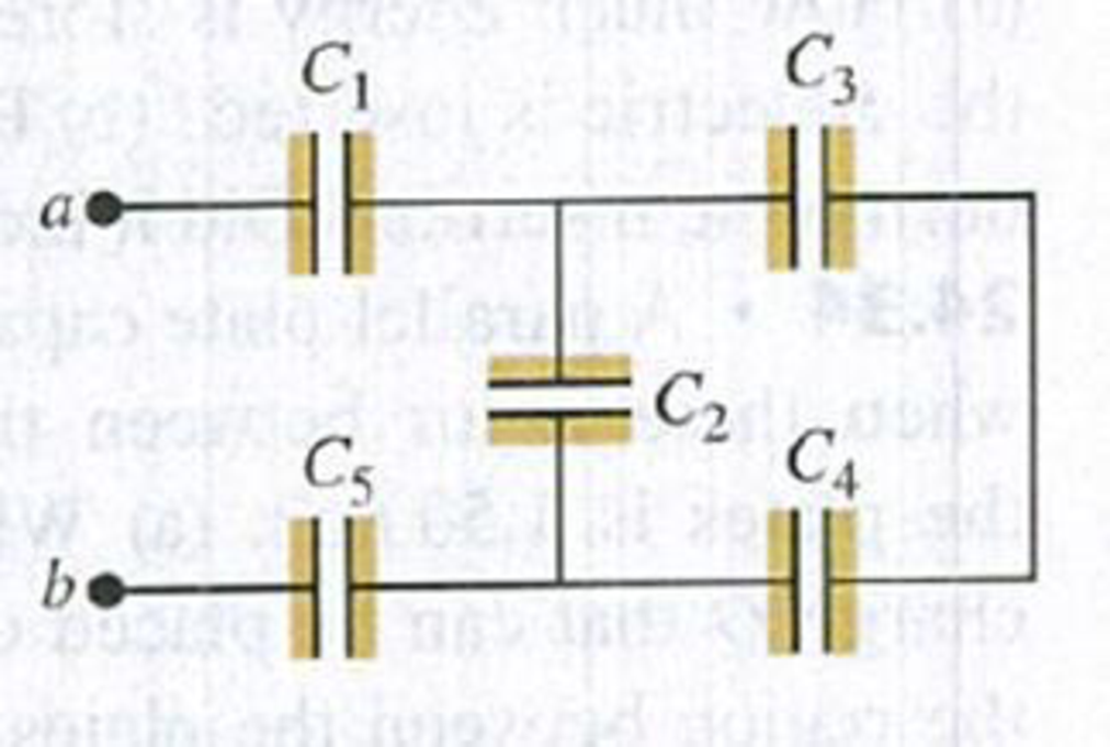
In Fig. P24.53, C1 = C5 = 8.4 μF and C2 = C3 = C4 = 4.2 μF. The applied potential is Vab = 220 V. (a) What is the equivalent capacitance of the network between points a and b? (b) Calculate the charge on each capacitor and the potential difference across each capacitor.
Figure P24.53
Expert Solution & Answer
Want to see the full answer?
Check out a sample textbook solution
Chapter 24 Solutions
University Physics (14th Edition)
Ch. 24 - Equation (24.2) shows that the capacitance of a...Ch. 24 - Suppose several different parallel-plate...Ch. 24 - Suppose the two plates of a capacitor have...Ch. 24 - To store the maximum amount of energy in a...Ch. 24 - In the parallel-plate capacitor of Fig. 24.2,...Ch. 24 - A parallel-plate capacitor is charged by being...Ch. 24 - A parallel-plate capacitor is charged by being...Ch. 24 - Two parallel-plate capacitors, identical except...Ch. 24 - The charged plates of a capacitor attract each...Ch. 24 - You have two capacitors and want to connect them...
Ch. 24 - As shown in Table 24.1, water has a very large...Ch. 24 - Is dielectric strength the same thing as...Ch. 24 - A capacitor made of aluminum foil strips separated...Ch. 24 - Suppose you bring a slab of dielectric close to...Ch. 24 - The freshness of fish can be measured by placing a...Ch. 24 - Electrolytic capacitors use as their dielectric an...Ch. 24 - In terms of the dielectric constant K, what...Ch. 24 - A parallel-plate capacitor is connected to a power...Ch. 24 - Liquid dielectrics that have polar molecules (such...Ch. 24 - A conductor is an extreme case of a dielectric,...Ch. 24 - The two plates of a capacitor are given charges Q....Ch. 24 - The plates of a parallel-plate capacitor are 2.50...Ch. 24 - The plates of a parallel-plate capacitor are 3.28...Ch. 24 - A parallel-plate air capacitor of capacitance 245...Ch. 24 - Cathode-ray-tube oscilloscopes have parallel metal...Ch. 24 - A 10.0-F parallel-plate capacitor with circular...Ch. 24 - A 5.00-F parallel-plate capacitor is connected to...Ch. 24 - A parallel-plate air capacitor is to store charge...Ch. 24 - A 5.00-pF, parallel-plate, air-filled capacitor...Ch. 24 - A capacitor is made from two hollow, coaxial, iron...Ch. 24 - A cylindrical capacitor consists of a solid inner...Ch. 24 - A spherical capacitor contains a charge of 3.30 nC...Ch. 24 - A cylindrical capacitor has an inner conductor of...Ch. 24 - A spherical capacitor is formed from two...Ch. 24 - Figure E24.14 shows a system of four capacitors,...Ch. 24 - BIO Electric Eels. Electric eels and electric fish...Ch. 24 - For the system of capacitors shown in Fig. E24.16,...Ch. 24 - In Fig. E24.17, each capacitor has C = 4.00 F and...Ch. 24 - In Fig. 24.8a, let C1 = 3.00 F, C2 = 5.00F, and...Ch. 24 - In Fig. 24.9a, let C1 = 3.00 F, C2 = 5.00 F, and...Ch. 24 - In Fig. E24.20, C1 = 6.00 F, C2 = 3 00 F, and C3 =...Ch. 24 - For the system of capacitors shown in Fig. E24.21,...Ch. 24 - Suppose the 3-F capacitor in Fig. 24.10a were...Ch. 24 - A 5.80-F, parallel-plate, air capacitor has a...Ch. 24 - A parallel-plate air capacitor has a capacitance...Ch. 24 - An air capacitor is made from two flat parallel...Ch. 24 - A parallel-plate vacuum capacitor has 8.38 J of...Ch. 24 - You have two identical capacitors and an external...Ch. 24 - For the capacitor net-work shown in Fig. E24.28,...Ch. 24 - For the capacitor net-work shown in Fig. E24.29,...Ch. 24 - A 0.350-m-long cylindrical capacitor consists of a...Ch. 24 - A cylindrical air capacitor of length 15.0 m...Ch. 24 - A capacitor is formed from two concentric...Ch. 24 - A 12.5-F capacitor is connected to a power supply...Ch. 24 - A parallel-plate capacitor has capacitance C0 =...Ch. 24 - Two parallel plates have equal and opposite...Ch. 24 - A budding electronics hobbyist wants to make a...Ch. 24 - The dielectric to be used in a parallel-plate...Ch. 24 - BIO Potential in Human Cells. Some cell walls in...Ch. 24 - A constant potential difference of 12 v is...Ch. 24 - Polystyrene has dielectric constant 2.6 and...Ch. 24 - When a 360-nF air capacitor (1 nF = 109F) is...Ch. 24 - A parallel-plate capacitor has capacitance C =...Ch. 24 - A parallel-plate capacitor has the volume between...Ch. 24 - A parallel-plate capacitor has plates with area...Ch. 24 - Electronic flash units for cameras contain a...Ch. 24 - A parallel-plate air capacitor is made by using...Ch. 24 - In one type of computer keyboard, each key holds a...Ch. 24 - BIO Cell Membranes. Cell membranes (the walled...Ch. 24 - A 20.0-F capacitor is charged to a potential...Ch. 24 - In Fig. 24.9a, let C1 = 9.0 F, C2 = 4.0 F, and Vab...Ch. 24 - For the capacitor network shown in Fig. P24.51,...Ch. 24 - In Fig. E24.17, C1 = 6.00 F, C2 = 3.00 F, C3 =...Ch. 24 - In Fig. P24.53, C1 = C5 = 8.4 F and C2 = C3 = C4 =...Ch. 24 - Current materials-science technology allows...Ch. 24 - In Fig. E24.20, C1 = 3.00 F and Vab = 150 V. The...Ch. 24 - The capacitors in Fig. P24.56 are initially...Ch. 24 - Three capacitors having capacitances of 8.4, 8.4,...Ch. 24 - Capacitance of a Thundercloud. The charge center...Ch. 24 - In Fig. P24.59, each capacitance C1 is 6.9 F, and...Ch. 24 - Each combination of capacitors between points a...Ch. 24 - A parallel-plate capacitor with only air between...Ch. 24 - An air capacitor is made by using two flat plates,...Ch. 24 - A potential difference Vab = 48.0 V is applied...Ch. 24 - CALC The inner cylinder of a long, cylindrical...Ch. 24 - A parallel-plate capacitor has square plates that...Ch. 24 - A parallel-plate capacitor is made from two plates...Ch. 24 - Three square metal plates A, B, and C, each 12.0...Ch. 24 - A fuel gauge uses a capacitor to determine the...Ch. 24 - DATA Your electronics company has several...Ch. 24 - DATA You are designing capacitors for various...Ch. 24 - DATA You are conducting experiments with an...Ch. 24 - Two square conducting plates with sides of length...Ch. 24 - BIO THE ELECTRIC EGG. Upon fertilization, the eggs...Ch. 24 - Suppose that the egg has a diameter of 200 m. What...Ch. 24 - Suppose that the change in Vm was caused by the...Ch. 24 - What is the minimum amount of work that must be...
Additional Science Textbook Solutions
Find more solutions based on key concepts
7. (II) A mass mat the end of a spring oscillates with a frequency of 0.83 Hz. When an additional 780-g mass is...
Physics: Principles with Applications
Αn atomic clock is taken to the North Pole, while another stays at the Equator. How far will they be out of syn...
Physics for Scientists and Engineers with Modern Physics
Does it ever make sense to say that one object is twice as hot as another? Does it matter whether one is referr...
An Introduction to Thermal Physics
The pV-diagram of the Carnot cycle.
Sears And Zemansky's University Physics With Modern Physics
20. (a) Determine the change in electric potential energy of a system of two charged objects when a charged ob...
College Physics
Two objects, one initially at rest, undergo a one-dimensional elastic collision. If half the kinetic energy of ...
Essential University Physics: Volume 1 (3rd Edition)
Knowledge Booster


Learn more about
Need a deep-dive on the concept behind this application? Look no further. Learn more about this topic, physics and related others by exploring similar questions and additional content below.Similar questions
- A disk of radius R (Fig. P24.49) has a nonuniform surface charge density = Cr, where C is a constant and r is measured from the center of the disk to a point on the surface of the disk. Find (by direct integration) the electric potential at P. Figure P24.49arrow_forwardA rod of length L (Fig. P24.25) lies along the x axis with its left end at the origin. It has a nonuniform charge density = x, where is a positive constant. (a) What are the units of ? (b) Calculate the electric potential at A. Figure P24.25 Problems 25 and 26.arrow_forwardAn electronics technician wishes to construct a parallel plate capacitor using rutile ( = 100) as the dielectric. The area of the plates is 1.00 cm2. What is the capacitance if the rutile thickness is 1.00 mm? (a) 88.5 pF (b) 177 pF (c) 8.85 F (d) 100 F (e) 35.4 Farrow_forward
- Two 5.00-nC charged particles are in a uniform electric field with a magnitude of 625 N/C. Each of the particles is moved from point A to point B along two different paths, labeled in Figure P26.65. a. Given the dimensions in the figure, what is the change in the electric potential experienced by the particle that is moved along path 1 (black)? b. What is the change in the electric potential experienced by the particle that is moved along path 2 (red)? c. Is there a path between the points A and B for which the change in the electric potential is different from your answers to parts (a) and (b)? Explain. FIGURE P26.65 Problems 65, 66, and 67.arrow_forwardAn electric dipole is located along the y axis as shown in Figure P24.48. The magnitude of its electric dipole moment is defined as p = 2aq. (a) At a point P, which is far from the dipole (r a), show that the electric potential is V=kepcosr2 (b) Calculate the radial component Er and the perpendicular component E of the associated electric field. Note that E = (1/r)(V/). Do these results seem reasonable for (c) = 90 and 0? (d) For r = 0? (e) For the dipole arrangement shown in Figure P24.48, express V in terms of Cartesian coordinates using r = (x2 + y2)1/2 and cos=y(x2+y2)1/2 (f) Using these results and again taking r a, calculate the field components Ex and Ey. Figure P24.48arrow_forwardThe thin, uniformly charged rod shown in Figure P24.41 has a linear charge density . Find an expression for the electric potential at P.arrow_forward
- FIGURE P26.14 Problems 14, 15, and 16. Four charged particles are at rest at the corners of a square (Fig. P26.14). The net charges are q1 = q2 = 2.65 C and q3 = q4 = 5.15 C. The distance between particle 1 and particle 3 is r13 = 1.75 cm. a. What is the electric potential energy of the four-particle system? b. If the particles are released from rest, what will happen to the system? In particular, what will happen to the systems kinetic energy as their separations become infinite?arrow_forwardTwo charged particles of equal magnitude are located along the y axis equal distances above and below the x axis as shown in Figure P24.14. (a) Plot a graph of the electric potential at points along the x axis over the interval 3a x 3a. You should plot the potential in units of keQ/a. (b) Let the charge of the particle located at y = a be negative. Plot the potential along the y axis over the interval 4a y 4a. Figure P24.14arrow_forwardFour charged particles are at rest at the corners of a square (Fig. P26.14). The net charges are q1 = q2 = 2.65 C and q3 = q4 = 5.15 C. The distance between particle 1 and particle 3 is r13 = 1.75 cm. a. What is the electric potential energy of the four-particle system? b. If the particles are released from rest, what will happen to the system? In particular, what will happen to the systems kinetic energy as their separations become infinite? FIGURE P26.14 Problems 14, 15, and 16.arrow_forward
- Figure P24.22 represents a graph of the electric potential in a region of space versus position x, where the electric field is parallel to the x axis. Draw a graph of the x component of the electric field versus x in this region. Figure P24.22arrow_forwardA spherical capacitor consists of a spherical conducting shell of radius b and charge 2Q that is concentric with a smaller conducting sphere of radius a and charge +Q (Fig. P20.36). (a) Show that its capacitance is C=abke(ba) (b) Show that as b approaches infinity, the capacitance approaches the value a/ke = 40a. Figure P20.36arrow_forwardA 5.00-nC charged particle is at point B in a uniform electric field with a magnitude of 625 N/C (Fig. P26.65). What is the change in electric potential experienced by the charge if it is moved from B to A along a. path 1 and b. path 2?arrow_forward
arrow_back_ios
SEE MORE QUESTIONS
arrow_forward_ios
Recommended textbooks for you
 Physics for Scientists and Engineers: Foundations...PhysicsISBN:9781133939146Author:Katz, Debora M.Publisher:Cengage Learning
 Principles of Physics: A Calculus-Based TextPhysicsISBN:9781133104261Author:Raymond A. Serway, John W. JewettPublisher:Cengage Learning
 Physics for Scientists and Engineers with Modern ...PhysicsISBN:9781337553292Author:Raymond A. Serway, John W. JewettPublisher:Cengage Learning
 Physics for Scientists and EngineersPhysicsISBN:9781337553278Author:Raymond A. Serway, John W. JewettPublisher:Cengage Learning
Physics for Scientists and Engineers: Foundations...
Physics
ISBN:9781133939146
Author:Katz, Debora M.
Publisher:Cengage Learning
Principles of Physics: A Calculus-Based Text
Physics
ISBN:9781133104261
Author:Raymond A. Serway, John W. Jewett
Publisher:Cengage Learning
Physics for Scientists and Engineers with Modern ...
Physics
ISBN:9781337553292
Author:Raymond A. Serway, John W. Jewett
Publisher:Cengage Learning
Physics for Scientists and Engineers
Physics
ISBN:9781337553278
Author:Raymond A. Serway, John W. Jewett
Publisher:Cengage Learning
Physics Capacitor & Capacitance part 7 (Parallel Plate capacitor) CBSE class 12; Author: LearnoHub - Class 11, 12;https://www.youtube.com/watch?v=JoW6UstbZ7Y;License: Standard YouTube License, CC-BY