
Videos
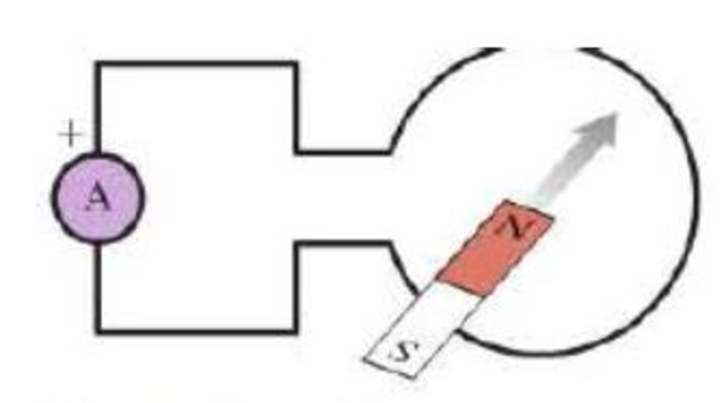
A magnet and a coil are oriented as shown in Figure P25.14. The magnet is moved rapidly into the coil, held stationary in the coil for a short time, and then rapidly pulled back out of the coil. Sketch a graph showing the reading of the ammeter as a function of time. The ammeter registers a positive value when current goes into the “ + ” terminal.
FIGURE P25.14
Want to see the full answer?
Check out a sample textbook solution
Chapter 25 Solutions
College Physics: A Strategic Approach Technology Update, Books a la Carte Edition; Modified Mastering Physics with Pearson eText -- ValuePack Access ... Physics: A Strategic Approach (3rd Edition)
Additional Science Textbook Solutions
Physics: Principles with Applications
Sears And Zemansky's University Physics With Modern Physics
College Physics (10th Edition)
University Physics Volume 1
An Introduction to Thermal Physics
Lecture- Tutorials for Introductory Astronomy


- A dish antenna having a diameter of 20.0 m receives (at normal incidence) a radio signal from a distant source as shown in Figure P24.63. The radio signal is a continuous sinusoidal wave with amplitude Emax = 0.200 V/m. Assume the antenna absorbs all the radiation that falls on the dish. (a) What is the amplitude of the magnetic field in this wave? (b) What is the intensity of the radiation received by this antenna? (c) What is the power received by the antenna? (d) What force is exerted by the radio waves on the antenna? Figure P24.63arrow_forwardA conducting rod is pulled with constant speed v on a smooth conducting rail as shown in Figure P32.77. A constant magnetic field B is directed into the page. If the speed of the bar is doubled, by what factor does the rate of heat dissipation change? FIGURE P32.77arrow_forwardA square loop with sides 1.0 m in length is placed in a magnetic field perpendicular to the plane of the loop. Half the area of the loop lies outside the magnetic field. The magnetic field varies with lime as B(t)=(0.0102.00t) T, where t is in seconds. The loop also has a battery of emf 12.0 V as shown in Figure P32.69. Determine the resultant emf of the circuit.arrow_forward
- An instrument based on induced emf has been used to measure projectile speeds up to 6 km/s. A small magnet is imbedded in the projectile as shown in Figure P23.2. The projectile passes through two coils separated by a distance d. As the projectile passes through each coil, a pulse of emf is induced in the coil. The time interval between pulses can be measured accurately with an oscilloscope, and thus the speed can be determined. (a) Sketch a graph of V versus t for the arrangement shown. Consider a current that flows counterclockwise as viewed from the starting point of the projectile as positive. On your graph, indicate which pulse is from coil 1 and which is from coil 2. (b) If the pulse separation is 2.40 ms and d = 1.50 m, what is the projectile speed? Figure P23.2arrow_forwardA loop of wire in the shape of a rectangle of width w and length L and a long, straight wire carrying a current I lie on a tabletop as shown in Figure P23.7. (a) Determine the magnetic flux through the loop due to the current I. (b) Suppose the current is changing with time according to I = a + bt, where a and b are constants. Determine the emf that is induced in the loop if b = 10.0 A/s, h = 1.00 cm, w = 10.0 cm, and L = 1.00 m. (c) What is the direction of the induced current in the rectangle? Figure P23.7arrow_forwardA uniform magnetic field B=5.44104iT passes through a closed surface with a slanted top as shown in Figure P31.59. a. Given the dimensions and orientation of the closed surface shown, what is the magnetic flux through the slanted top of the surface? b. What is the net magnetic flux through the entire closed surface?arrow_forward
- A dish antenna with a diameter of 20.0 m receives (at normal incidence) a radio signal from a distant source, as shown in Figure P21.73. The radio signal is a continuous sinusoidal wave with amplitude Emax = 0.20 V/m. Assume the antenna absorbs all the radiation that falls on the dish. (a) What is the amplitude of the magnetic field in this Figure P21.73 wave? (b) What is the intensity of the radiation received by the antenna? (c) What is the power received by the antenna?arrow_forwardSuppose a uniform magnetic field is perpendicular to the 81211-in. page of your homework and a rectangular metal loop lies on the page. The loops sides line up with the edges of the page. The magnetic field is changing with time as described by B = 3.75 103 t, where B is in teslas and t is in seconds. a. Is the magnetic field increasing or decreasing? b. Find the magnitude of the emf induced in the loop.arrow_forwardThe magnetic field through a square loop of wire with sides of length 3.00 cm changes with time as shown in Figure P32.8, where the sign indicates the direction of the field relative to the axis of the loop. Plot the emf induced in the loop versus time. FIGURE P32.8arrow_forward
- A dish antenna with a diameter of 20.0 m receives (at normal incidence) a radio signal from a distant source, as shown in Figure P21.73. The radio signal is a continuous sinusoidal wave with amplitude Emax = 0.20 V/m. Assume the antenna absorbs all the radiation that falls on the dish. (a) What is the amplitude of the magnetic field in this Figure P21.73 wave? (b) What is the intensity of the radiation received by the antenna? (c) What is the power received by the antenna?arrow_forwardA conducting rod of length moves with velocity v parallel to a long wire carrying a steady current I. The axis of the rod is maintained perpendicular to the wire with the near end a distance r away (Fig. P30.44). Show that the magnitude of the emf induced in the rod is E=0Iv2ln(1+lr) Figure P30.44arrow_forwardConsider an electromagnetic wave traveling in the positive y direction. The magnetic field associated with the wave at some location at some instant points in the negative x direction as shown in Figure OQ24.12. What is the direction of the electric field at this position and at this instant? (a) the positive x direction (b) the positive y direction (c) the positive z direction (d) the negative z direction (e) the negative y direction Figure OQ24.12arrow_forward
 Physics for Scientists and Engineers: Foundations...PhysicsISBN:9781133939146Author:Katz, Debora M.Publisher:Cengage Learning
 Physics for Scientists and EngineersPhysicsISBN:9781337553278Author:Raymond A. Serway, John W. JewettPublisher:Cengage Learning
 Physics for Scientists and Engineers with Modern ...PhysicsISBN:9781337553292Author:Raymond A. Serway, John W. JewettPublisher:Cengage Learning
 Principles of Physics: A Calculus-Based TextPhysicsISBN:9781133104261Author:Raymond A. Serway, John W. JewettPublisher:Cengage Learning
 College PhysicsPhysicsISBN:9781285737027Author:Raymond A. Serway, Chris VuillePublisher:Cengage Learning
 College PhysicsPhysicsISBN:9781305952300Author:Raymond A. Serway, Chris VuillePublisher:Cengage Learning