UNIVERSITY PHYSICS UCI PKG
11th Edition
ISBN: 9781323575208
Author: YOUNG
Publisher: PEARSON C
expand_more
expand_more
format_list_bulleted
Videos
Textbook Question
Chapter 25, Problem 25.66P
In the circuit shown in Fig. P25.66, R is a variable resistor whose value ranges from 0 to ∞, and a and b are the terminals of a battery that has an emf ε = 15.0 V and an internal resistance of 4.00 Ω. The ammeter and voltmeter are idealized meters. As R varies over its full range of values, what will be the largest and smallest readings of (a) the voltmeter and (b) the ammeter? (c) Sketch qualitative graphs of the readings of both meters as functions of R.
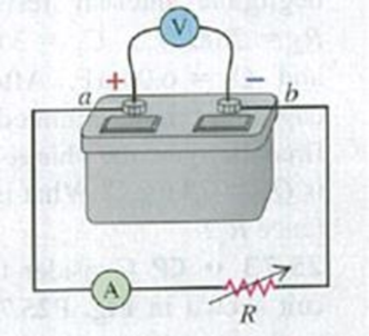
Figure P25.66
Expert Solution & Answer
Want to see the full answer?
Check out a sample textbook solution
Students have asked these similar questions
25.54. In the circuit shown in
Fig. P25.54, R is a variable resistor whose
value ranges from 0 to co, and a and b are
the terminals of a battery that has an emf
E = 15.0V and an internal resistance of
4.00 2. The ammeter and voltmeter are
idealized meters. As R varies over its full
range of values, what will be the largest
and smallest readings of (a) the voltmeter
and (b) the ammeter? (c) Sketch qualita-
tive graphs of the readings of both meters
as functions of R.
Figure P25.54
R
You have a circuit consisting of a power supply,
switch, resistor, two capacitors, and
voltage/current probes. The resistor has the
value R1 = (1.8 ± 10%) MQ. The capacitors have
%3D
the values C1 = (0.6 ± 20%) µF and C2 = (2.2 ±
20%) µF. The logger pro data resembles the plot
below.
40
35
30
25
20
15
10
1 2 3
5 6
8 9 10 11 12 13 14 15 16 17 18 19 20 21 22 23 24 25
a)
Label the title and all the axes on the
plot above. Identify which region corresponds
to the capacitors charging and discharging. Be
sure to include appropriate units (MKS).
When switch S in Fig. E25.33 is open, the voltmeter V of the battery reads 3.08 V. When the switch is closed, the voltmeter reading drops to 2.97 V, and the ammeter A reads 1.65 A. Find the emf, the internal resistance of the battery, and the circuit resistance R. Assume that the two meters are ideal, so they don’t affect the circuit.
Chapter 25 Solutions
UNIVERSITY PHYSICS UCI PKG
Ch. 25.1 - Suppose we replaced the wire in Example 25.1 with...Ch. 25.2 - Prob. 25.2TYUCh. 25.3 - Suppose you increase the voltage across the copper...Ch. 25.4 - Rank the following circuits in order from highest...Ch. 25.5 - Rank the following circuits in order from highest...Ch. 25.6 - Which of the following factors will, if increased,...Ch. 25 - The definition of resistivity ( = E/J) implies...Ch. 25 - A cylindrical rod has resistance R. If we triple...Ch. 25 - A cylindrical rod has resistivity . If we triple...Ch. 25 - Two copper wires with different diameters are...
Ch. 25 - When is a 1.5-V AAA battery not actually a 1.5-V...Ch. 25 - Can the potential difference between the terminals...Ch. 25 - A rule of thumb used to determine the internal...Ch. 25 - Batteries are always labeled with their emf; for...Ch. 25 - We have seen that a coulomb is an enormous amount...Ch. 25 - Electrons in an electric circuit pass through a...Ch. 25 - Temperature coefficients of resistivity are given...Ch. 25 - Which of the graphs in Fig. Q25.12 best...Ch. 25 - Why does an electric light bulb nearly always burn...Ch. 25 - A light bulb glows because it has resistance. The...Ch. 25 - (See Discussion Question Q25.14.) An ideal ammeter...Ch. 25 - (See Discussion Question Q25.14.) Will a light...Ch. 25 - The energy that can be extracted from a storage...Ch. 25 - Eight flashlight batteries in series have an cmf...Ch. 25 - Small aircraft often have 24-V electrical systems...Ch. 25 - Long-distance, electric-power, transmission lines...Ch. 25 - Ordinary household electric lines in North America...Ch. 25 - A fuse is a device designed to break a circuit,...Ch. 25 - High-voltage power supplies are sometimes designed...Ch. 25 - The text states that good thermal conductors are...Ch. 25 - Lightning Strikes. During lightning strikes from a...Ch. 25 - A silver wire 2.6 mm in diameter transfers a...Ch. 25 - A 5.00-A current runs through a 12-gauge copper...Ch. 25 - An 18-gauge copper wire (diameter 1.02 mm) carries...Ch. 25 - Copper has 8.5 1028 free electrons per cubic...Ch. 25 - Prob. 25.6ECh. 25 - CALC The current in a wire varies with time...Ch. 25 - Current passes through a solution of sodium...Ch. 25 - BIO Transmission of Nerve Impulses. Nerve cells...Ch. 25 - (a) At room temperature, what is the strength of...Ch. 25 - A 1.50-m cylindrical rod of diameter 0.500 cm is...Ch. 25 - A copper wire has a square cross section 2.3 mm on...Ch. 25 - Prob. 25.13ECh. 25 - Prob. 25.14ECh. 25 - A cylindrical tungsten filament 15.0 cm long with...Ch. 25 - A ductile metal wire has resistance R. What will...Ch. 25 - Prob. 25.17ECh. 25 - Prob. 25.18ECh. 25 - Prob. 25.19ECh. 25 - Prob. 25.20ECh. 25 - A current-carrying gold wire has diameter 0.84 mm....Ch. 25 - A hollow aluminum cylinder is 2.50 m long and has...Ch. 25 - Prob. 25.23ECh. 25 - A carbon resistor is to be used as a thermometer....Ch. 25 - A copper transmission cable 100 km long and 10.0...Ch. 25 - Consider the circuit shown in Fig. E25.26. The...Ch. 25 - An ideal voltmeter V is connected to a 2.0-11...Ch. 25 - An idealized ammeter is connected to a battery as...Ch. 25 - When switch S in Fig. E25.29 is open, the...Ch. 25 - The circuit shown in Fig. E25.30 contains two...Ch. 25 - In the circuit shown in Fig. E25.30, the 16.0-V...Ch. 25 - In the circuit of Fig. E25.30, the 5.0- resistor...Ch. 25 - The circuit shown in Fig. E25.33 contains two...Ch. 25 - When a resistor with resistance R is connected to...Ch. 25 - Light Bulbs. The power rating of a light bulb...Ch. 25 - If a 75-W" bulb (see Problem 25.35) is connected...Ch. 25 - European Light Bulb. In Europe the standard...Ch. 25 - A battery-powered global positioning system (GPS)...Ch. 25 - Consider the circuit of Fig. E25.30. (a) What is...Ch. 25 - BIO Electric Eels. Electric eels generate electric...Ch. 25 - BIO Treatment of Heart Failure. A heart...Ch. 25 - The battery for a certain cell phone is rated at...Ch. 25 - Prob. 25.43ECh. 25 - An idealized voltmeter is connected across the...Ch. 25 - A 25.0- bulb is connected across the terminals of...Ch. 25 - A typical small flashlight contains two batteries,...Ch. 25 - In the circuit in Fig. E25.47, find (a) the rate...Ch. 25 - A 540-W electric heater is designed to operate...Ch. 25 - Prob. 25.49ECh. 25 - In an ionic solution, a current consists of Ca2+...Ch. 25 - An electrical conductor designed to carry large...Ch. 25 - An overhead transmission cable for electrical...Ch. 25 - On your first day at work as an electrical...Ch. 25 - A 2.0-m length of wire is made by welding the end...Ch. 25 - A 3.00-m length of copper wire at 20 C has a...Ch. 25 - A heating clement made of tungsten wire is...Ch. 25 - CP BIO Struck by Lightning. Lightning strikes can...Ch. 25 - A resistor with resistance R is connected to a...Ch. 25 - CALC A material of resistivity is formed into a...Ch. 25 - CALC The region between two concentric conducting...Ch. 25 - The potential difference across the terminals of a...Ch. 25 - (a) What is the potential difference Vad in the...Ch. 25 - BIO The average bulk resistivity of the human body...Ch. 25 - BIO A person with body resistance between his...Ch. 25 - A typical cost for electrical power is 0,120 per...Ch. 25 - In the circuit shown in Fig. P25.66, R is a...Ch. 25 - A Nonideal Ammeter. Unlike the idealized ammeter...Ch. 25 - A cylindrical copper cable 1.50 km long is...Ch. 25 - CALC A 1.50-m cylinder of radius 1.10 cm is made...Ch. 25 - Compact Fluorescent Bulbs. Compact fluorescent...Ch. 25 - Prob. 25.71PCh. 25 - CP Consider the circuit shown in Fig. P25.72. The...Ch. 25 - CP Consider the circuit shown in Fig. P25.73. The...Ch. 25 - DATA An external resistor R is connected between...Ch. 25 - DATA The voltage drop Vab across each of resistors...Ch. 25 - DATA According to the U.S. National Electrical...Ch. 25 - Prob. 25.77CPCh. 25 - An external resistor with resistance R is...Ch. 25 - BIO SPIDERWEB CONDUCTIVITY. Some types of spiders...Ch. 25 - BIO SPIDERWEB CONDUCTIVITY. Some types of spiders...Ch. 25 - BIO SPIDERWEB CONDUCTIVITY. Some types of spiders...Ch. 25 - BIO SPIDERWEB CONDUCTIVITY. Some types of spiders...
Additional Science Textbook Solutions
Find more solutions based on key concepts
Interior Heat. Compare the surface area–to–volume ratios (that is, total surface area divided by total volume) ...
Life in the Universe (4th Edition)
21.20 Two point charges are placed on the .x -axis as follows: Charge q1 = +4.00 nC is located at x = 0.200 m, ...
University Physics (14th Edition)
Choose the best answer to each of the following. Explain your reasoning. Which moon shows evidence of rainfall ...
The Cosmic Perspective Fundamentals (2nd Edition)
12. Take a spring and cut it in half to make two springs. Is the spring constant of these smaller springs large...
College Physics: A Strategic Approach (4th Edition)
11. (II) What is the linear speed, due to the Earth's rotation, of a point (a) on the equator, (b) on the Arcti...
Physics: Principles with Applications
Jupiters major moons keep getting stretched in different directions by tidal forces. What force causes these mo...
Conceptual Integrated Science
Knowledge Booster


Learn more about
Need a deep-dive on the concept behind this application? Look no further. Learn more about this topic, physics and related others by exploring similar questions and additional content below.Similar questions
- The emf source, ɛ=4.5 V, of the circuit shown in the figure has negligible internal resistance. The resistors have resistances R1=2 Q and R2=4.7 Q. The capacitor has a capacitance C=4.9 µF. Determine the time constant t, in units of microseconds, for charging the capacitor. What is the charge Q on the capacitor in units of microcoulomb?arrow_forwardYou have a circuit with a battery hooked up to 2 capacitors in Parallel. The battery has a voltage of 4.3 V. The capacitors have a value of C1 = 40.0 µF and C2 = 25.0 u F. While finding the actual voltage is very helpful, it's hard to use this as a prediction because not all batteries are the same. So one way to look at this is a percentage. Even if the voltage of the battery is different, the percentage of the voltage should be the same regardless. Find the percentage of the battery voltage that is across capacitor 1. To find percentages: • Find the voltage across the specific capacitor just like previously Divide this voltage by the voltage of the battery • Multiply your answer by 100 to turn it into a percent Your answer should include: 2 Decimal Places Correct SI Units Your Answer:arrow_forwardThe emf source, ε=4.5 V, of the circuit shown in the figure has negligible internal resistance. The resistors have resistances R1=2 Ω and R2=4.7 Ω. The capacitor has a capacitance C=4.9 μF. Determine the time constant τ, in units of microseconds, for charging the capacitor. What is the charge Q on the capacitor in units of microcoulomb?arrow_forward
- A charged capacitor is connected to a resistor and a switch as in the figure below. The circuit has a time constant of 1.30 s. Soon after the switch is closed, the charge on the capacitor is 69.0% of its initial charge. S +Q C R (a) Find the time interval required for the capacitor to reach this charge. S (b) If R = 220 k2, what is the value of C? C = µFarrow_forwardThe capacitor in the circuit shown below is initially uncharged. The switch is closed at t = 0 s. AVbattery = 24 V, C = 3.0 μF, and R = 2.0 Q. At sometime after the switch is closed, the voltage across the resistor is measured to be 16 V. What is the charge on the capacitor at this time, in µC? Your answer needs to have 2 significant figures, including the negative sign in your answer if needed. Do not include the positive sign if the answer is positive. No unit is needed in your answer, it is already given in the question statement.arrow_forwardthe emf source, E=3.2 V, of the circuit shown in the figure has negligible internal resistance. the resistors have resistances R1=3 ohm and R2=4.2 ohm. the capacitor has a capacitance C= 4.5uF. A) determine the time constant t , in units of microseconds for charging the capacitor. B) what is the charge Q on the capacitor in units of microcoulomb?arrow_forward
- In physics, the half-life is often used to characterize exponential decay of physical quantities such as radioactive substances. The half-life is the time required for the quantity to decay to half of its initial value. The time constant for the voltage on a capacitance discharging through a resistance is τ=RC. Find an expression for the half-life of the voltage in terms of R and C.arrow_forwardEngineering students at the University of Houston can take classes where they learn about the theory of electrical circuits. One topic they encounter in these courses is called “Ohm’s law,” and it describes the relationship between the voltage V across a resistor, the electrical current I passing through the resistor, and a quantity R known as the resistance. The law can be written as follows:V = I * R.Voltage is typically measured in volts, while current is measured in amperes (amps), and resistance is measured in ohms where 1 ohm equals 1 volt/amp. Lastly, in circuits with variable resistance, the quantities V, I, and R can depend on time.(a) Differentiate Ohm’s Law to find an equation relating the quantities V, I, R, dV/dt , dI/dt , and dR/dt .(b) Suppose that in an electrical circuit the current is increasing at a rate of 0.5 amps per second and the resistance is decreasing at a rate of 4 ohms per second. If at this same moment in time there are 3 volts of voltage and 2 ohms of…arrow_forwardAn initially uncharged capacitor of capacitance C=199μF, and a resistor with a resistance R= 6.5k2 are connected to a battery with a voltage V=20V as shown in the figure below. The switch is closed at r=0. What would be the voltage across the capacitor one time constant after the switch is closed? Express your answer in units volts using one decimal place. Yanıtınızı ekleyin. S VI R www C ...arrow_forward
- Three capacitors with capacitances C1 = C, C2 = 3C, and C3 = 5C, are in a circuit as shown. The source has potential difference ΔV = 17 V. It is observed that one plate of the capacitor C3 has a charge of q = 5 mC. Write an expression for the capacitance C (that is, the capacitance of the first capacitor), in terms of q and ΔV.arrow_forwardTwo capacitors are connected in a circuit in series. The capacitances are C1 = 18 μF, and C2 = 8.5 μF and Ctot=5.77μF. Calculate the numerical value of Q in C given ΔV = 19 V.arrow_forwardA circuit with a resistance R = 88 Ω is connected to a battery with potential difference across the terminals of ΔV = 6.5 V. a. Input an expression for the current passing through the circuit, I. (b) What is the current in milliamps, mA? (c) If the resistance of the circuit was increased by a factor of ten, Rnew = 10R, what is the new current in milliamps, mA?arrow_forward
arrow_back_ios
SEE MORE QUESTIONS
arrow_forward_ios
Recommended textbooks for you
 College PhysicsPhysicsISBN:9781305952300Author:Raymond A. Serway, Chris VuillePublisher:Cengage Learning
 University Physics (14th Edition)PhysicsISBN:9780133969290Author:Hugh D. Young, Roger A. FreedmanPublisher:PEARSON
 Introduction To Quantum MechanicsPhysicsISBN:9781107189638Author:Griffiths, David J., Schroeter, Darrell F.Publisher:Cambridge University Press
 Physics for Scientists and EngineersPhysicsISBN:9781337553278Author:Raymond A. Serway, John W. JewettPublisher:Cengage Learning
 Lecture- Tutorials for Introductory AstronomyPhysicsISBN:9780321820464Author:Edward E. Prather, Tim P. Slater, Jeff P. Adams, Gina BrissendenPublisher:Addison-Wesley
 College Physics: A Strategic Approach (4th Editio...PhysicsISBN:9780134609034Author:Randall D. Knight (Professor Emeritus), Brian Jones, Stuart FieldPublisher:PEARSON
College Physics
Physics
ISBN:9781305952300
Author:Raymond A. Serway, Chris Vuille
Publisher:Cengage Learning
University Physics (14th Edition)
Physics
ISBN:9780133969290
Author:Hugh D. Young, Roger A. Freedman
Publisher:PEARSON
Introduction To Quantum Mechanics
Physics
ISBN:9781107189638
Author:Griffiths, David J., Schroeter, Darrell F.
Publisher:Cambridge University Press
Physics for Scientists and Engineers
Physics
ISBN:9781337553278
Author:Raymond A. Serway, John W. Jewett
Publisher:Cengage Learning
Lecture- Tutorials for Introductory Astronomy
Physics
ISBN:9780321820464
Author:Edward E. Prather, Tim P. Slater, Jeff P. Adams, Gina Brissenden
Publisher:Addison-Wesley
College Physics: A Strategic Approach (4th Editio...
Physics
ISBN:9780134609034
Author:Randall D. Knight (Professor Emeritus), Brian Jones, Stuart Field
Publisher:PEARSON
DC Series circuits explained - The basics working principle; Author: The Engineering Mindset;https://www.youtube.com/watch?v=VV6tZ3Aqfuc;License: Standard YouTube License, CC-BY