
University Physics (14th Edition)
14th Edition
ISBN: 9780133969290
Author: Hugh D. Young, Roger A. Freedman
Publisher: PEARSON
expand_more
expand_more
format_list_bulleted
Videos
Textbook Question
Chapter 25, Problem 25.74P
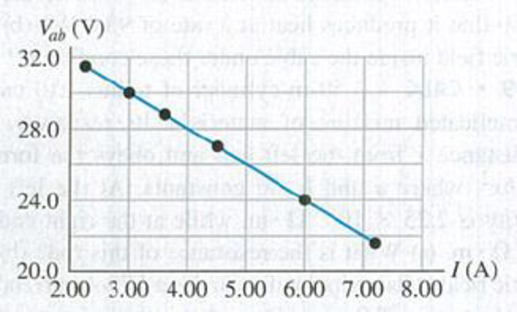
DATA An external resistor R is connected between the terminals of a battery. The value of R varies. For each R value, the current I in the circuit and the terminal voltage Vab of the battery are measured. The results are plotted in Fig. F25.74, a graph of Vab versus I that shows the best straight-line fit to the data, (a) Use the graph in Fig. P25.74 to calculate the battery’s emf and internal resistance, (b) For what value of R is Vab equal to 80.0% of the battery emf?
Figure P25.74
Expert Solution & Answer

Trending nowThis is a popular solution!

Chapter 25 Solutions
University Physics (14th Edition)
Ch. 25 - The definition of resistivity ( = E/J) implies...Ch. 25 - A cylindrical rod has resistance R. If we triple...Ch. 25 - A cylindrical rod has resistivity . If we triple...Ch. 25 - Two copper wires with different diameters are...Ch. 25 - When is a 1.5-V AAA battery not actually a 1.5-V...Ch. 25 - Can the potential difference between the terminals...Ch. 25 - A rule of thumb used to determine the internal...Ch. 25 - Batteries are always labeled with their emf; for...Ch. 25 - We have seen that a coulomb is an enormous amount...Ch. 25 - Electrons in an electric circuit pass through a...
Ch. 25 - Temperature coefficients of resistivity are given...Ch. 25 - Which of the graphs in Fig. Q25.12 best...Ch. 25 - Why does an electric light bulb nearly always burn...Ch. 25 - A light bulb glows because it has resistance. The...Ch. 25 - (See Discussion Question Q25.14.) An ideal ammeter...Ch. 25 - (See Discussion Question Q25.14.) Will a light...Ch. 25 - The energy that can be extracted from a storage...Ch. 25 - Eight flashlight batteries in series have an cmf...Ch. 25 - Small aircraft often have 24-V electrical systems...Ch. 25 - Long-distance, electric-power, transmission lines...Ch. 25 - Ordinary household electric lines in North America...Ch. 25 - A fuse is a device designed to break a circuit,...Ch. 25 - High-voltage power supplies are sometimes designed...Ch. 25 - The text states that good thermal conductors are...Ch. 25 - Lightning Strikes. During lightning strikes from a...Ch. 25 - A silver wire 2.6 mm in diameter transfers a...Ch. 25 - A 5.00-A current runs through a 12-gauge copper...Ch. 25 - An 18-gauge copper wire (diameter 1.02 mm) carries...Ch. 25 - Copper has 8.5 1028 free electrons per cubic...Ch. 25 - Prob. 25.6ECh. 25 - CALC The current in a wire varies with time...Ch. 25 - Current passes through a solution of sodium...Ch. 25 - BIO Transmission of Nerve Impulses. Nerve cells...Ch. 25 - (a) At room temperature, what is the strength of...Ch. 25 - A 1.50-m cylindrical rod of diameter 0.500 cm is...Ch. 25 - A copper wire has a square cross section 2.3 mm on...Ch. 25 - Prob. 25.13ECh. 25 - Prob. 25.14ECh. 25 - A cylindrical tungsten filament 15.0 cm long with...Ch. 25 - A ductile metal wire has resistance R. What will...Ch. 25 - Prob. 25.17ECh. 25 - Prob. 25.18ECh. 25 - Prob. 25.19ECh. 25 - Prob. 25.20ECh. 25 - A current-carrying gold wire has diameter 0.84 mm....Ch. 25 - A hollow aluminum cylinder is 2.50 m long and has...Ch. 25 - Prob. 25.23ECh. 25 - A carbon resistor is to be used as a thermometer....Ch. 25 - A copper transmission cable 100 km long and 10.0...Ch. 25 - Consider the circuit shown in Fig. E25.26. The...Ch. 25 - An ideal voltmeter V is connected to a 2.0-11...Ch. 25 - An idealized ammeter is connected to a battery as...Ch. 25 - When switch S in Fig. E25.29 is open, the...Ch. 25 - The circuit shown in Fig. E25.30 contains two...Ch. 25 - In the circuit shown in Fig. E25.30, the 16.0-V...Ch. 25 - In the circuit of Fig. E25.30, the 5.0- resistor...Ch. 25 - The circuit shown in Fig. E25.33 contains two...Ch. 25 - When a resistor with resistance R is connected to...Ch. 25 - Light Bulbs. The power rating of a light bulb...Ch. 25 - If a 75-W" bulb (see Problem 25.35) is connected...Ch. 25 - European Light Bulb. In Europe the standard...Ch. 25 - A battery-powered global positioning system (GPS)...Ch. 25 - Consider the circuit of Fig. E25.30. (a) What is...Ch. 25 - BIO Electric Eels. Electric eels generate electric...Ch. 25 - BIO Treatment of Heart Failure. A heart...Ch. 25 - The battery for a certain cell phone is rated at...Ch. 25 - Prob. 25.43ECh. 25 - An idealized voltmeter is connected across the...Ch. 25 - A 25.0- bulb is connected across the terminals of...Ch. 25 - A typical small flashlight contains two batteries,...Ch. 25 - In the circuit in Fig. E25.47, find (a) the rate...Ch. 25 - A 540-W electric heater is designed to operate...Ch. 25 - Prob. 25.49ECh. 25 - In an ionic solution, a current consists of Ca2+...Ch. 25 - An electrical conductor designed to carry large...Ch. 25 - An overhead transmission cable for electrical...Ch. 25 - On your first day at work as an electrical...Ch. 25 - A 2.0-m length of wire is made by welding the end...Ch. 25 - A 3.00-m length of copper wire at 20 C has a...Ch. 25 - A heating clement made of tungsten wire is...Ch. 25 - CP BIO Struck by Lightning. Lightning strikes can...Ch. 25 - A resistor with resistance R is connected to a...Ch. 25 - CALC A material of resistivity is formed into a...Ch. 25 - CALC The region between two concentric conducting...Ch. 25 - The potential difference across the terminals of a...Ch. 25 - (a) What is the potential difference Vad in the...Ch. 25 - BIO The average bulk resistivity of the human body...Ch. 25 - BIO A person with body resistance between his...Ch. 25 - A typical cost for electrical power is 0,120 per...Ch. 25 - In the circuit shown in Fig. P25.66, R is a...Ch. 25 - A Nonideal Ammeter. Unlike the idealized ammeter...Ch. 25 - A cylindrical copper cable 1.50 km long is...Ch. 25 - CALC A 1.50-m cylinder of radius 1.10 cm is made...Ch. 25 - Compact Fluorescent Bulbs. Compact fluorescent...Ch. 25 - Prob. 25.71PCh. 25 - CP Consider the circuit shown in Fig. P25.72. The...Ch. 25 - CP Consider the circuit shown in Fig. P25.73. The...Ch. 25 - DATA An external resistor R is connected between...Ch. 25 - DATA The voltage drop Vab across each of resistors...Ch. 25 - DATA According to the U.S. National Electrical...Ch. 25 - Prob. 25.77CPCh. 25 - An external resistor with resistance R is...Ch. 25 - BIO SPIDERWEB CONDUCTIVITY. Some types of spiders...Ch. 25 - BIO SPIDERWEB CONDUCTIVITY. Some types of spiders...Ch. 25 - BIO SPIDERWEB CONDUCTIVITY. Some types of spiders...Ch. 25 - BIO SPIDERWEB CONDUCTIVITY. Some types of spiders...
Additional Science Textbook Solutions
Find more solutions based on key concepts
Two identical bubbles of gas form at the bottom of a lake, then rise to the surface. Because the pressure is mu...
An Introduction to Thermal Physics
The diagram shows Bob’s view of the passing of two identical spaceships. Anna’s and his own, where v=2 . The le...
Modern Physics
3. What is free-fall, and why does it make you weightless? Briefly describe why astronauts are weightless in th...
The Cosmic Perspective (8th Edition)
The magnitude and direction of particle’s velocity.
Physics (5th Edition)
12. If two spinning objects have the same angular momentum, will they necessarily have the same rotational kine...
College Physics (10th Edition)
Using the definitions in Eqs. 1.1 and 1.4, and appropriate diagrams, show that the dot product and cross produc...
Introduction to Electrodynamics
Knowledge Booster


Learn more about
Need a deep-dive on the concept behind this application? Look no further. Learn more about this topic, physics and related others by exploring similar questions and additional content below.Similar questions
- In Figure P29.81, N real batteries, each with an emf and internal resistance r, are connected in a closed ring. A resistor R can be connected across any two points of this ring, causing there to be n real batteries in one branch and N n resistors in the other branch. Find an expression for the current through the resistor R in this case.arrow_forwardThe circuit shown in Figure P28.78 is set up in the laboratory to measure an unknown capacitance C in series with a resistance R = 10.0 M powered by a battery whose emf is 6.19 V. The data given in the table are the measured voltages across the capacitor as a function of lime, where t = 0 represents the instant at which the switch is thrown to position b. (a) Construct a graph of In (/v) versus I and perform a linear least-squares fit to the data, (b) From the slope of your graph, obtain a value for the time constant of the circuit and a value for the capacitance. v(V) t(s) In (/v) 6.19 0 5.56 4.87 4.93 11.1 4.34 19.4 3.72 30.8 3.09 46.6 2.47 67.3 1.83 102.2arrow_forwardFigure P18.37 shows a simplified model of a cardiac defibrillator, a device used to patients in ventricular fibrillation. When the switch S is toggled to the left, the capacitor C charges through the resistor R .When the switch is toggled to the right, the capacitor discharges current through the patients torso, modeled as the resistor Rtorso, allowing the hearts normal rhythm to be reestablished. (a) If the capacitor is initially uncharged with C = 8.00 F and = 1250 V, find the value of R required to charge the capacitor to a voltage of 775 V in 1.50 s. (b) If the capacitor is then discharged across the patients torso with, Rtorso = 1250 , calculate the voltage across the capacitor after 5.00 ms. Figure P18.37arrow_forward
- Figure P18.37 shows a simplified model of a cardiac defibrillator, a device used to patients in ventricular fibrillation. When the switch S is toggled to the left, the capacitor C charges through the resistor R .When the switch is toggled to the right, the capacitor discharges current through the patients torso, modeled as the resistor Rtorso, allowing the hearts normal rhythm to be reestablished. (a) If the capacitor is initially uncharged with C = 8.00 F and = 1250 V, find the value of R required to charge the capacitor to a voltage of 775 V in 1.50 s. (b) If the capacitor is then discharged across the patients torso with, Rtorso = 1250 , calculate the voltage across the capacitor after 5.00 ms. Figure P18.37arrow_forwardA capacitor with initial charge Q0 is connected across a resistor R at time t = 0. The separation between the plates of the capacitor changes as d = d0/(1 + t) for 0 t 1 s. Find an expression for the voltage drop across the capacitor as a function of time.arrow_forward(a) What is the average power output of a heart defibrillator that dissipates 400 J of energy in 10.0 ms? (b) Considering the high-power output, why doesn’t the defibrillator produce serious bums?arrow_forward
- Two ideal emf devices are connected to a set of resistors as shown in Figure P29.47. Find an expression for the emf 2 in terms of 1, R1, R2, R3, R4, and the current through R4, labeled I1.arrow_forwardFigure P29.77 shows a circuit with two batteries and three resistors. a. How much current flows through the 2.00- resistor? b. What is the potential difference between points a and b in the circuit?arrow_forwardA battery is used to charge a capacitor through a resistor as shown in Figure P27.44. Show that half the energy supplied by the battery appears as internal energy in the resistor and half is stored in the capacitor. Figure P27.44arrow_forward
- Electric current I enters a node with three resistors connected in parallel (Fig. CQ18.5). Which one of the following is correct? (a) I1 = I and I2 = I3 = 0. (b) I2 I1 and I2 I3. (c) V1 V2 V3 (d) I1 I2 I3 0. Figure CQ18.5arrow_forwardIn the circuit of Figure P27.25, the switch S has been open for a long time. It is then suddenly closed. Take = 10.0 V, R1 = 50.0 k, R2 = 100 k, and C = 10.0 F. Determine the time constant (a) before the switch is closed and (b) after the switch is closed. (c) Let the switch be closed at t = 0. Determine the current in the switch as a function of time. Figure P27.25 Problems 25 and 26.arrow_forwardWhat is the equivalent resistance between points a and b of the six resistors shown in Figure P29.70? FIGURE P29.70arrow_forward
arrow_back_ios
SEE MORE QUESTIONS
arrow_forward_ios
Recommended textbooks for you
 Physics for Scientists and Engineers with Modern ...PhysicsISBN:9781337553292Author:Raymond A. Serway, John W. JewettPublisher:Cengage Learning
 Principles of Physics: A Calculus-Based TextPhysicsISBN:9781133104261Author:Raymond A. Serway, John W. JewettPublisher:Cengage Learning
 Physics for Scientists and Engineers: Foundations...PhysicsISBN:9781133939146Author:Katz, Debora M.Publisher:Cengage Learning
 College PhysicsPhysicsISBN:9781305952300Author:Raymond A. Serway, Chris VuillePublisher:Cengage Learning
 Physics for Scientists and Engineers, Technology ...PhysicsISBN:9781305116399Author:Raymond A. Serway, John W. JewettPublisher:Cengage Learning
 College PhysicsPhysicsISBN:9781285737027Author:Raymond A. Serway, Chris VuillePublisher:Cengage Learning
Physics for Scientists and Engineers with Modern ...
Physics
ISBN:9781337553292
Author:Raymond A. Serway, John W. Jewett
Publisher:Cengage Learning
Principles of Physics: A Calculus-Based Text
Physics
ISBN:9781133104261
Author:Raymond A. Serway, John W. Jewett
Publisher:Cengage Learning
Physics for Scientists and Engineers: Foundations...
Physics
ISBN:9781133939146
Author:Katz, Debora M.
Publisher:Cengage Learning
College Physics
Physics
ISBN:9781305952300
Author:Raymond A. Serway, Chris Vuille
Publisher:Cengage Learning
Physics for Scientists and Engineers, Technology ...
Physics
ISBN:9781305116399
Author:Raymond A. Serway, John W. Jewett
Publisher:Cengage Learning
College Physics
Physics
ISBN:9781285737027
Author:Raymond A. Serway, Chris Vuille
Publisher:Cengage Learning
DC Series circuits explained - The basics working principle; Author: The Engineering Mindset;https://www.youtube.com/watch?v=VV6tZ3Aqfuc;License: Standard YouTube License, CC-BY