
Videos
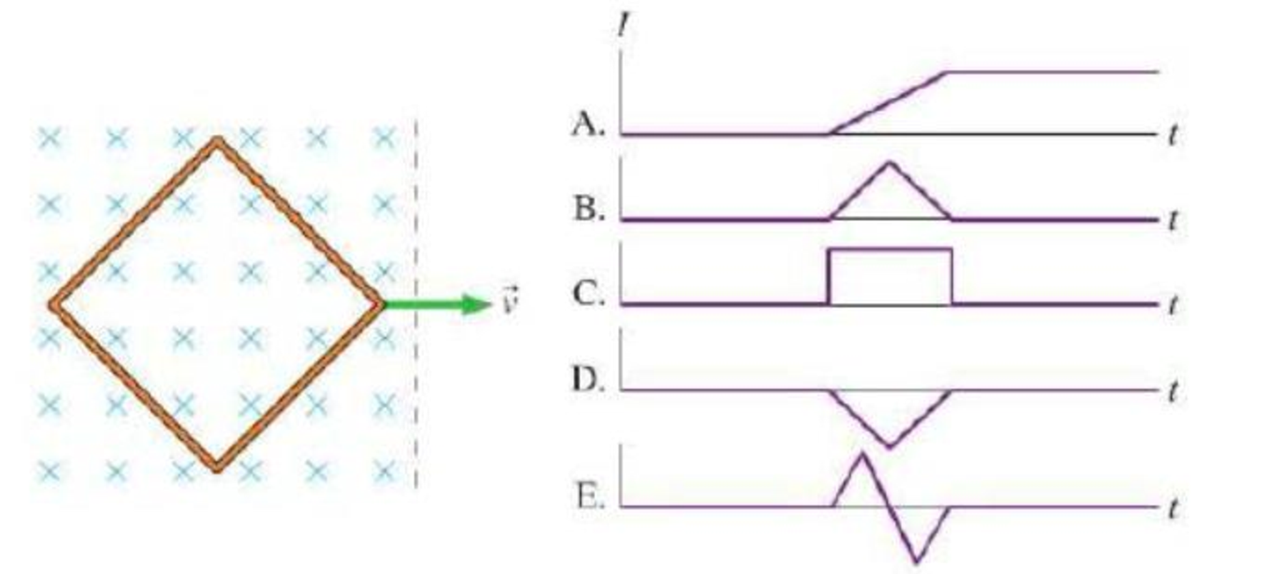
A diamond-shaped loop of wire is pulled at a constant velocity through a region where the magnetic field is directed into the paper in the left half and is zero in the right half, as shown in Figure Q25.28. As the loop moves from left to right, which graph best represents the induced current in the loop as a function of time? Let a clockwise current be positive and a counter-clockwise current be negative.
FIGURE Q25.28
Want to see the full answer?
Check out a sample textbook solution
Chapter 25 Solutions
Modified Mastering Physics with Pearson eText -- Standalone Access Card -- for College Physics: A Strategic Approach (4th Edition)
Additional Science Textbook Solutions
Essential University Physics: Volume 2 (3rd Edition)
Cosmic Perspective Fundamentals
Sears And Zemansky's University Physics With Modern Physics
Conceptual Integrated Science
Conceptual Physics (12th Edition)
University Physics with Modern Physics (14th Edition)


- A uniform magnetic field B=5.44104iT passes through a closed surface with a slanted top as shown in Figure P31.59. a. Given the dimensions and orientation of the closed surface shown, what is the magnetic flux through the slanted top of the surface? b. What is the net magnetic flux through the entire closed surface?arrow_forwardFigure P32.21 shows a circular conducting loop with a 5.00-cm radius and a total resistance of 1.30 placed within a uniform magnetic field pointing into the page. a. What is the rate at which the magnetic field is changing if a counterclockwise current I = 4.60 102 A is induced in the loop? b. Is the induced current caused by an increase or a decrease in the magnetic field with time?arrow_forwardA constant magnetic field of 0.275 T points through a circular loop of wire with radius 3.50 cm as shown in Figure P32.1. a. What is the magnetic flux through the loop? b. Is a current induced in the loop? Explain. FIGURE P32.1arrow_forward
- A bar magnet is dropped through a loop of wire as shown in Figure P32.64. a. What is the direction of the induced current as the magnet is approaching the loop, as viewed from above where the magnet begins? b. What is the direction of the induced current after the magnet falls through and is receding from the loop, as viewed from above where the magnet began? FIGURE P32.64arrow_forwardSuppose a uniform magnetic field is perpendicular to the 81211-in. page of your homework and a rectangular metal loop lies on the page. The loops sides line up with the edges of the page. The magnetic field is changing with time as described by B = 3.75 103 t, where B is in teslas and t is in seconds. a. Is the magnetic field increasing or decreasing? b. Find the magnitude of the emf induced in the loop.arrow_forwardA time-dependent uniform magnetic field of magnitude B(t) is confined in a cylindrical region of radius R. A conducting rod of length 2D is placed in the region, as shown below. Show that the emf between the ends of the rod is given by dBdtDR2D2 . ( Hint: To find the between the ends, we need to integrate the electric field from one end to the other. To find the electric field, use Faraday’s law as “Ampere’s law for E”.)arrow_forward
- A thin conducting bar (60.0 cm long) aligned in the positive y direction is moving with velocity v=(1.25m/s)i in a region with a spatially uniform 0.400-T magnetic field directed at an angle of 36.0 above the xy plane. a. What is the magnitude of the emf induced along the length of the moving bar? b. Which end of the bar is positively charged?arrow_forwardA conducting rod is pulled with constant speed v on a smooth conducting rail as shown in Figure P32.77. A constant magnetic field B is directed into the page. If the speed of the bar is doubled, by what factor does the rate of heat dissipation change? FIGURE P32.77arrow_forwardFigure P30.11 shows three configurations of wires and the resultant magnetic fields due to current in the wires. What is the direction of the current that gives the resultant magnetic field shown in each case?arrow_forward
- Two infinitely long current-carrying wires run parallel in the xy plane and are each a distance d = 11.0 cm from the y axis (Fig. P30.83). The current in both wires is I = 5.00 A in the negative y direction. a. Draw a sketch of the magnetic field pattern in the xz plane due to the two wires. What is the magnitude of the magnetic field due to the two wires b. at the origin and c. as a function of z along the z axis, at x = y = 0? FIGURE P30.83arrow_forwardFigure P30.10 shows a circular current-carrying wire. Using the coordinate system indicated (with the z axis out of the page), state the direction of the magnetic field at points A and B.arrow_forwardUnreasonable results Frustrated by the small Hall voltage obtained in blood flow measurements, a medical physicist decides to increase the applied magnetic field strength to get a 0.500-V output for blood moving at 30.0 cm/s in a 1.50-cm-diameter vessel. (a) What magnetic field strength is needed? (b) What is unreasonable about this result? (C) Which premise is responsible?arrow_forward
 Physics for Scientists and Engineers: Foundations...PhysicsISBN:9781133939146Author:Katz, Debora M.Publisher:Cengage Learning
 Glencoe Physics: Principles and Problems, Student...PhysicsISBN:9780078807213Author:Paul W. ZitzewitzPublisher:Glencoe/McGraw-Hill
 College PhysicsPhysicsISBN:9781285737027Author:Raymond A. Serway, Chris VuillePublisher:Cengage Learning
 Physics for Scientists and Engineers with Modern ...PhysicsISBN:9781337553292Author:Raymond A. Serway, John W. JewettPublisher:Cengage Learning
 Principles of Physics: A Calculus-Based TextPhysicsISBN:9781133104261Author:Raymond A. Serway, John W. JewettPublisher:Cengage Learning
 Physics for Scientists and Engineers, Technology ...PhysicsISBN:9781305116399Author:Raymond A. Serway, John W. JewettPublisher:Cengage Learning