
Concept explainers
Videos
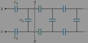
Some physical systems possessing capacitance continuously distributed over space can be modeled as an infinite array of discrete circuit elements. Examples are a microwave waveguide and the axon of a nerve cell. To practice analysis of an infinite array, determine the equivalent capacitance C between terminals X and Y of the infinite set of capacitors represented in Figure P25.47. Each capacitor has capacitance C0. Suggestions: Imagine that the ladder is cut at the line AB and note that the equivalent capacitance of the infinite section to the right of AB is also C.

Trending nowThis is a popular solution!

Chapter 25 Solutions
Bundle: Physics for Scientists and Engineers, Volume 2, Loose-leaf Version, 10th + WebAssign Printed Access Card for Serway/Jewett's Physics for Scientists and Engineers, 10th, Multi-Term


- Consider the combination of capacitors in Figure P16.42. (a) Find the equivalent single capacitance of the two capacitors in series and redraw the diagram (called diagram 1) with this equivalent capacitance. (b) In diagram 1, find the equivalent capacitance of the three capacitors in parallel and redraw the diagram as a single battery and single capacitor in a loop. (c) Compute the charge on the single equivalent capacitor. (d) Returning to diagram 1, compute the charge on each individual capacitor. Does the sum agree with the value found in part (c)? (e) What is the charge on the 24.0-F capacitor and on the 8.00-F capacitor? Compute the voltage drop across (f) the 24.0-F capacitor and (g) the 8.00-F capacitor. Figure P16.42arrow_forwardA parallel-plate capacitor with vacuum between its horizontal plates has a capacitance of 25.0 F. A nonconducting liquid with dielectric constant 6.50 is poured into the space between the plates, filling up a fraction f of its volume. (a) Find the new capacitance as a function of f. (b) What should you expect the capacitance to be when f = 0? Does your expression from part (a) agree with your answer? (c) What capacitance should you expect when f = 1? Does the expression from part (a) agree with your answer?arrow_forwardA spherical capacitor is formed from two concentric spherical conducting shells separated by a vacuum. The inner sphere has radius 12.5 cm and the outer sphere has radius 14.8 cm. A potential difference of 120 V is appLied to the capacitor, (a) What is the energy density at r = 12.6 cm, just outside the inner sphere? (b) What is the energy density at r = 14.7 cm, just inside the outer sphere? (c) For the parallel-plate capacitor the energy density is uniform in the region between the plates, except near the edges of the plates. Is this also true for the spherical capacitor?arrow_forward
- A Pairs of parallel wires or coaxial cables are two conductors separated by an insulator, so they have a capacitance. For a given cable, the capacitance is independent of the length if the cable is very long. A typical circuit model of a cable is shown in Figure P27.87. It is called a lumped-parameter model and represents how a unit length of the cable behaves. Find the equivalent capacitance of a. one unit length (Fig. P27.87A), b. two unit lengths (Fig. P27.87B), and c. an infinite number of unit lengths (Fig. P27.87C). Hint: For the infinite number of units, adding one more unit at the beginning does not change the equivalent capacitance.arrow_forwardConsider an infinitely long network with identical capacitors arranged as shown in Figure P27.82. Determine the equivalent capacitance of such a network. Each capacitor has a capacitance of 1.00 F.arrow_forwardA spherical capacitor is formed from two concentric spherical conducting spheres separated by vacuum. Tire inner sphere has radius 12.5 cm and the outer sphere has radius 14.8 cm. A potential difference of 120 V is applied to the capacitor, (a) What is the capacitance of the capacitor? tb) What is the magnitude of the electrical field at r = 12.6 cm, just outside the inner sphere? (c) What is the magnitude of the electrical field at r = 14.7 cm, just inside the outer sphere? (d) For a parallel-plate capacitor the electrical field is uniform in the region between the plates, except near the edges of the plates. Is this also true for a spherical capacitor?arrow_forward
- Figure P27.75 shows four capacitors with CA = 4.00 F, CB = 8.00 F. CC = 6.00 F. and CD = 5.00 F connected across points a and b, which have potential difference Vab = 12.0 V. a. What is the equivalent capacitance of the four capacitors? b. What is the charge on each of the four capacitors?arrow_forwardThe separation between the 4.40-cm2 plates of an air-filled parallel-plate capacitor is 0.230 cm. a. What is the capacitance of this capacitor? If the capacitor is connected to a 9.00-V battery, find b. the charge stored by the capacitor and c. the magnitude of the electric field between its plates.arrow_forwardUnreasonable Results (a) An 8.00 F capacitor is connected in parallel to another capacitor, producing a total capacitance of 5.00 F. What is the capacitance of the second capacitor? (b) What is unreasonable about this result? (C) Which assumptions are unreasonable or inconsistent?arrow_forward
- Four parallel metal plates P1, P2, P3, and P4, each of area 7.50 cm2, are separated successively by a distance d = 1.19 mm as shown in Figure P25.34. Plate P1 is connected to the negative terminal of a battery, and P2 is connected to the positive terminal. The battery maintains a potential difference of 12.0 V. (a) If P3 is connected to the negative terminal, what is the capacitance of the three-plate system P1P2P3? (b) What is the charge on P2? (c) If P4 is now connected to the positive terminal, what is the capacitance of the four-plate system P1P2P3P4? (d) What is the charge on P4?arrow_forwardA charge Q is placed on a capacitor of capacitance C. The capacitor is connected into the circuit shown in Figure P26.37, with an open switch, a resistor, and an initially uncharged capacitor of capacitance 3C. The switch is then closed, and the circuit comes to equilibrium. In terms of Q and C, find (a) the final potential difference between the plates of each capacitor, (b) the charge on each capacitor, and (c) the final energy stored in each capacitor. (d) Find the internal energy appearing in the resistor. Figure P26.37arrow_forwardConsider the combination of capacitors in Figure P16.42. (a) Find the equivalent single capacitance of the two capacitors in series and redraw the diagram (called diagram 1) with this equivalent capacitance. (b) In diagram 1, find the equivalent capacitance of the three capacitors in parallel and redraw the diagram as a single battery and single capacitor in a loop. (c) Compute the charge on the single equivalent capacitor. (d) Returning to diagram 1, compute the charge on each individual capacitor. Does the sum agree with the value found in part (c)? (e) What is the charge on the 24.0-F capacitor and on the 8.00-F capacitor? Compute the voltage drop across (f) the 24.0-F capacitor and (g) the 8.00-F capacitor. Figure P16.42arrow_forward
 Physics for Scientists and EngineersPhysicsISBN:9781337553278Author:Raymond A. Serway, John W. JewettPublisher:Cengage Learning
 Physics for Scientists and Engineers with Modern ...PhysicsISBN:9781337553292Author:Raymond A. Serway, John W. JewettPublisher:Cengage Learning
 Physics for Scientists and Engineers: Foundations...PhysicsISBN:9781133939146Author:Katz, Debora M.Publisher:Cengage Learning
 College PhysicsPhysicsISBN:9781285737027Author:Raymond A. Serway, Chris VuillePublisher:Cengage Learning
 College PhysicsPhysicsISBN:9781305952300Author:Raymond A. Serway, Chris VuillePublisher:Cengage Learning
 Principles of Physics: A Calculus-Based TextPhysicsISBN:9781133104261Author:Raymond A. Serway, John W. JewettPublisher:Cengage Learning