
Concept explainers
Videos
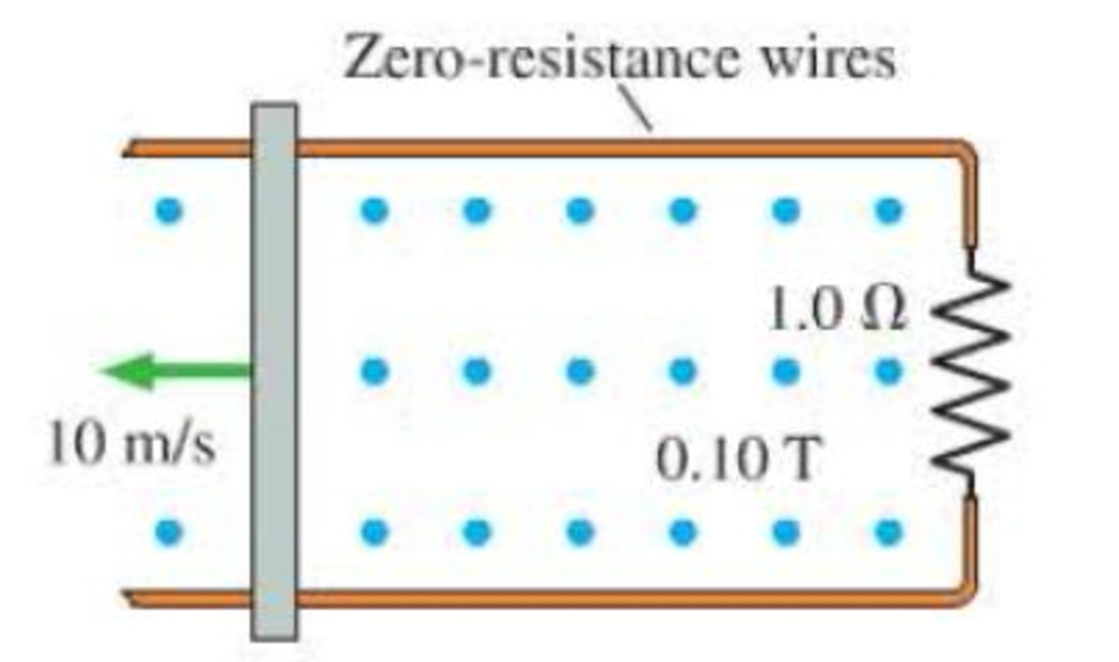
A 20-cm-long, zero-resistance wire is pulled outward, on zero-resistance rails, at a steady speed of 10 m/s in a 0.10 T magnetic field. (See Figure P25.63.) On the opposite side, a 1.0 Ω carbon resistor completes the circuit by connecting the two rails. The mass of the resistor is 50 mg.
a. What is the induced current in the circuit?
b. How much force is needed to pull the wire at this speed?
c. How much does the temperature of the carbon increase if the wire is pulled for 10 s? The specific heat of carbon is 710 J/kg · K. Neglect thermal energy transfer out of the resistor.
FIGURE P25.63
Want to see the full answer?
Check out a sample textbook solution
Chapter 25 Solutions
College Physics: A Strategic Approach, Books a la Carte Edition (4th Edition)
Additional Science Textbook Solutions
Conceptual Physics (12th Edition)
Essential University Physics (3rd Edition)
The Cosmic Perspective
Essential University Physics: Volume 1 (3rd Edition)
Applied Physics (11th Edition)
Physics for Scientists and Engineers with Modern Physics


- A bar magnet is dropped through a loop of wire as shown in Figure P32.64. a. What is the direction of the induced current as the magnet is approaching the loop, as viewed from above where the magnet begins? b. What is the direction of the induced current after the magnet falls through and is receding from the loop, as viewed from above where the magnet began? FIGURE P32.64arrow_forwardFigure P32.21 shows a circular conducting loop with a 5.00-cm radius and a total resistance of 1.30 placed within a uniform magnetic field pointing into the page. a. What is the rate at which the magnetic field is changing if a counterclockwise current I = 4.60 102 A is induced in the loop? b. Is the induced current caused by an increase or a decrease in the magnetic field with time?arrow_forwardA uniform magnetic field B=5.44104iT passes through a closed surface with a slanted top as shown in Figure P31.59. a. Given the dimensions and orientation of the closed surface shown, what is the magnetic flux through the slanted top of the surface? b. What is the net magnetic flux through the entire closed surface?arrow_forward
- Figure P30.11 shows three configurations of wires and the resultant magnetic fields due to current in the wires. What is the direction of the current that gives the resultant magnetic field shown in each case?arrow_forwardAn instrument based on induced emf has been used to measure projectile speeds up to 6 km/s. A small magnet is imbedded in the projectile as shown in Figure P23.2. The projectile passes through two coils separated by a distance d. As the projectile passes through each coil, a pulse of emf is induced in the coil. The time interval between pulses can be measured accurately with an oscilloscope, and thus the speed can be determined. (a) Sketch a graph of V versus t for the arrangement shown. Consider a current that flows counterclockwise as viewed from the starting point of the projectile as positive. On your graph, indicate which pulse is from coil 1 and which is from coil 2. (b) If the pulse separation is 2.40 ms and d = 1.50 m, what is the projectile speed? Figure P23.2arrow_forwardA dish antenna with a diameter of 20.0 m receives (at normal incidence) a radio signal from a distant source, as shown in Figure P21.73. The radio signal is a continuous sinusoidal wave with amplitude Emax = 0.20 V/m. Assume the antenna absorbs all the radiation that falls on the dish. (a) What is the amplitude of the magnetic field in this Figure P21.73 wave? (b) What is the intensity of the radiation received by the antenna? (c) What is the power received by the antenna?arrow_forward
- The Hall effect finds important application in the electronics industry. It is used to find the sign and density of the carriers of electric current in semiconductor chips. The arrangement is shown in Figure P22.66. A semiconducting block of thickness t and width d carries a current I in the x direction. A uniform magnetic field B is applied in the y direction. If the charge carriers are positive, the magnetic force deflects them in the z direction. Positive charge accumulates on the top surface of the sample and negative charge on the bottom surface, creating a downward electric field. In equilibrium, the downward electric force on the charge carriers balances the upward magnetic force and the carriers move through the sample without deflection. The Hall voltage ΔVH = Vc − Va between the top and bottom surfaces is measured, and the density of the charge carriers can be calculated from it. (a) Demonstrate that if the charge carriers are negative the Hall voltage will be negative. Hence, the Hall effect reveals the sign of the charge carriers, so the sample can be classified as p-type (with positive majority charge carriers) or n-type (with negative). (b) Determine the number of charge carriers per unit volume n in terms of I, t, B, ΔVH, and the magnitude q of the carrier charge. Figure P22.66arrow_forwardTwo infinitely long current-carrying wires run parallel in the xy plane and are each a distance d = 11.0 cm from the y axis (Fig. P30.83). The current in both wires is I = 5.00 A in the negative y direction. a. Draw a sketch of the magnetic field pattern in the xz plane due to the two wires. What is the magnitude of the magnetic field due to the two wires b. at the origin and c. as a function of z along the z axis, at x = y = 0? FIGURE P30.83arrow_forwardA conducting rod is pulled with constant speed v on a smooth conducting rail as shown in Figure P32.77. A constant magnetic field B is directed into the page. If the speed of the bar is doubled, by what factor does the rate of heat dissipation change? FIGURE P32.77arrow_forward
- A dish antenna with a diameter of 20.0 m receives (at normal incidence) a radio signal from a distant source, as shown in Figure P21.73. The radio signal is a continuous sinusoidal wave with amplitude Emax = 0.20 V/m. Assume the antenna absorbs all the radiation that falls on the dish. (a) What is the amplitude of the magnetic field in this Figure P21.73 wave? (b) What is the intensity of the radiation received by the antenna? (c) What is the power received by the antenna?arrow_forwardConsider the system pictured in Figure P28.26. A 15.0-cm horizontal wire of mass 15.0 g is placed between two thin, vertical conductors, and a uniform magnetic field acts perpendicular to the page. The wire is free to move vertically without friction on the two vertical conductors. When a 5.00-A current is directed as shown in the figure, the horizontal wire moves upward at constant velocity in the presence of gravity. (a) What forces act on the horizontal wire, and (b) under what condition is the wire able to move upward at constant velocity? (c) Find the magnitude and direction of the minimum magnetic Field required to move the wire at constant speed. (d) What happens if the magnetic field exceeds this minimum value? Figure P28.26arrow_forward
 College PhysicsPhysicsISBN:9781285737027Author:Raymond A. Serway, Chris VuillePublisher:Cengage Learning
 Physics for Scientists and Engineers with Modern ...PhysicsISBN:9781337553292Author:Raymond A. Serway, John W. JewettPublisher:Cengage Learning
 Physics for Scientists and Engineers: Foundations...PhysicsISBN:9781133939146Author:Katz, Debora M.Publisher:Cengage Learning
 Principles of Physics: A Calculus-Based TextPhysicsISBN:9781133104261Author:Raymond A. Serway, John W. JewettPublisher:Cengage Learning
 Physics for Scientists and EngineersPhysicsISBN:9781337553278Author:Raymond A. Serway, John W. JewettPublisher:Cengage Learning
 Physics for Scientists and Engineers, Technology ...PhysicsISBN:9781305116399Author:Raymond A. Serway, John W. JewettPublisher:Cengage Learning