Videos
(a)
The reading on the voltmeter when
(a)
Answer to Problem 91P
The reading of the voltmeter is
Explanation of Solution
Given:
The resistance
The resistance
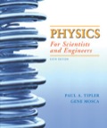
The given diagram is shown in Figure 1
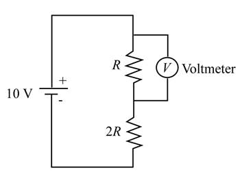
Figure 1
Formula:
The expression to determine the equivalent resistance of the circuit is given by,
The expression to determine the value of the current in the circuit is given by,
The expression for the voltage reading of the voltmeter is given by,
Calculation:
The reading of the voltmeter is calculated as,
Conclusion:
Therefore, the reading of the voltmeter is
(b)
The reading of the voltmeter.
(b)
Answer to Problem 91P
The reading of the voltmeter is
Explanation of Solution
Given:
The resistance
Formula:
The expression for the voltage reading of the voltmeter is given by,
Calculation:
The reading of the voltmeter is calculated as,
Conclusion:
Therefore, the reading of the voltmeter is
(c)
The reading of the voltmeter.
(c)
Answer to Problem 91P
The reading of the voltmeter is
Explanation of Solution
Given:
The resistance
Formula:
The expression for the voltage reading of the voltmeter is given by,
Calculation:
The reading of the voltmeter is calculated as,
Conclusion:
Therefore, the reading of the voltmeter is
(d)
The reading of the voltmeter.
(d)
Answer to Problem 91P
The reading of the voltmeter is
Explanation of Solution
Given:
The resistance
Formula:
The expression for the voltage reading of the voltmeter is given by,
Calculation:
The reading of the voltmeter is calculated as,
Conclusion:
Therefore, the reading of the voltmeter is
(e)
The reading of the voltmeter.
(e)
Answer to Problem 91P
The reading of the voltmeter is
Explanation of Solution
Given:
The resistance
Formula:
The expression for the voltage reading of the voltmeter is given by,
Calculation:
The reading of the voltmeter is calculated as,
Conclusion:
Therefore, the reading of the voltmeter is
(f)
The maximum possible value of the resistance
(f)
Answer to Problem 91P
The maximum value of
Explanation of Solution
Given:
The measured voltage is to be within ten percent of the true voltage.
Formula:
The condition for the voltage is given by,
The expression for the current
The expression for the true voltage is given by,
Calculation:
The expression to determine the resistance is evaluated as,
Conclusion:
Therefore, the maximum value of
Want to see more full solutions like this?
Chapter 25 Solutions
EBK PHYSICS FOR SCIENTISTS AND ENGINEER


- A 2.00- and a 7.50-F capacitor can be connected in series or parallel, as can a 25.0- and a 100k resistor. Calculate the four RC time constants possible from connecting the resulting capacitance and resistance in series.arrow_forwardThe switch on an RC circuit is closed at t = 0. Given thate = 6.0 V, R = 92 Ω, and C = 28 mF, how much charge is on thecapacitor at time t = 4.0 ms?arrow_forwardUsing the exact exponential treatment, find how much time is required to charge an initially uncharged 50-uF (micro-Farad) capacitor through a 75 M-Ohm (mega-ohm) resistor to 60.0% of its final voltage. Group of answer choices a)320 days b)57 minutes c)3.2x10^-2 sec d)4.5 minutesarrow_forward
- The switch on an RC circuit is closed at t = 0.Given that E = 9.0 V, R = 99 Ωand C = 28 μF , how much charge is on the capacitor at time t= 4.2 ms?arrow_forwardYou connect a 10.0 MΩ resistor in series with a 3.20 mFcapacitor and a battery with emf 9.00 V. Before you close the switchat t = 0 to complete the circuit, the capacitor is uncharged. Find the fraction of the initial current present at t = 18.0 sarrow_forwardIn Fig. 27-26, the ideal batterieshave emfs E1=150 V and E2=50 Vand the resistances are R1 = 3.0 0 andR2 = 2.0 0. If the potential at P is 100 V,what is it at Q?arrow_forward
 College PhysicsPhysicsISBN:9781938168000Author:Paul Peter Urone, Roger HinrichsPublisher:OpenStax College
 Glencoe Physics: Principles and Problems, Student...PhysicsISBN:9780078807213Author:Paul W. ZitzewitzPublisher:Glencoe/McGraw-Hill