Videos
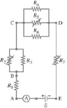
Given the circuit shown in Fig. 26–34, use the words “increases,” “decreases,” or “stays the same” to complete the following statements:
(a) If R7 increases, the potential difference between A and E _____. Assume no resistance in Ⓐ and
(b) If R7 increases, the potential difference between A and E _____. Assume Ⓐ and
(c) If R7 increases, the voltage drop across R4 __________.
(d) If R2 decreases, the current through R1 __________.
(e) If R2 decreases, the current through R6 __________.
(f) If R2 decreases, the current through R6 _____.
(g) If R5 increases, the voltage drop across R2 _____.
(h) If R5, increases, the voltage drop across R4 _____.
(i) If R2, R5, and R7 increase.
FIGURE 26–34 Question 15. R2. R5, and R7 are variable resistors (you can change their resistance), given the symbol  .
.
Want to see the full answer?
Check out a sample textbook solution
Chapter 26 Solutions
Modified Mastering Physics with Pearson eText -- Standalone Access Card -- for Physics for Scientists & Engineers with Modern Physics
Additional Science Textbook Solutions
Physics (5th Edition)
The Cosmic Perspective Fundamentals (2nd Edition)
College Physics: A Strategic Approach (4th Edition)
The Cosmic Perspective (8th Edition)
University Physics Volume 2
Applied Physics (11th Edition)


- Check Your Understanding Consider the electrical circuits in your home. Give at least two of circuits that must use a combination of series and parallel circuits to operate efficiently.arrow_forwardSuppose you wanted to charge an initially uncharged 110 pF capacitor through a 55 MΩ resistor to 90.0% of its final voltage. How much time (in s) would be required to do this?arrow_forwardWhy should you not connect an ammeter directly across a voltage source as shown in Figure 21.51? (Note that script E in the figure stands for emf.)arrow_forward
- Just curious as to how they got 292 ohms in the first part of the problem. Thanks.arrow_forward. (III) What would the current be in Fig. 19–61 if the 12- Ωresistor is shorted out (resistance= 0 )? Let = 0 r = 1.0 Ω .arrow_forwardFor the circuit shown in Fig.a 20.0 Ω resistor is embedded in a large block of ice at 0.00°C, and the battery has negligible internal resistance. At what rate (in g /s) is this circuit melting the ice?arrow_forward
- Can a copper wire and an aluminum wire of the samelength have the same resistance? Explainarrow_forwardSuppose a n electrical wire is replaced with one having every linear dimension doubled (i.e., the length and radius h ave twice their original values). Does the wire now h ave (a) more resistance, (b) less resistance, o r (c) the same resistance than before?arrow_forwardIs it possible to connect a group of resistors of value R in such a waythat the equivalent resistance is less than R? If so, give a specificexamplearrow_forward
- Hi, here's my question. 26.60: In the figure, find the emf e in order for the current through the 7.00 W resistor to be 18.0 A. Each emf source has negligible internal resistance.arrow_forwardCalculate the magnitude and direction of the durrents in each resistor of fig. 19-58. There are two solutions to this problem given on the website. However, both are leaveing out steps.arrow_forward
