
Videos
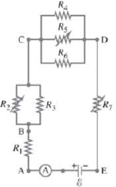
Given the circuit shown in Fig. 26–34, use the words “increases,” “decreases,” or “stays the same” to complete the following statements:
(a) If R7 increases, the potential difference between A and E _____. Assume no resistance in Ⓐ and
(b) If R7 increases, the potential difference between A and E _____. Assume Ⓐ and
(c) If R7 increases, the voltage drop across R4 __________.
(d) If R2 decreases, the current through R1 __________.
(e) If R2 decreases, the current through R6 __________.
(f) If R2 decreases, the current through R6 _____.
(g) If R5 increases, the voltage drop across R2 _____.
(h) If R5, increases, the voltage drop across R4 _____.
(i) If R2, R5, and R7 increase.
FIGURE 26–34 Question 15. R2. R5, and R7 are variable resistors (you can change their resistance), given the symbol  .
.
Want to see the full answer?
Check out a sample textbook solution
Chapter 26 Solutions
Pearson eText -- Physics for Scientists and Engineers with Modern Physics -- Instant Access (Pearson+)
Additional Science Textbook Solutions
Physics (5th Edition)
The Cosmic Perspective Fundamentals (2nd Edition)
College Physics: A Strategic Approach (4th Edition)
The Cosmic Perspective (8th Edition)
University Physics Volume 2
Applied Physics (11th Edition)


- Q- Given that V = 24 Volts, Find E in the circuit below. R = 62 R = 42 | |av R- 162 R,-12 24 V R.412 R, - 62 R:-242 R, = 82 R,- 82arrow_forward(II) What is the net resistance of the circuit connected to the battery in Fig. 19–50? R R C ww B ww R V R FIGURE 19-50 R A Problems 19 and 20. wwarrow_forward4) Based on the circuit to the right answer the folowing questbons, SHOW ALL WORK ourrent flows h STEADY STATE (a) The equivalent capacitance and resistance is 20uF c2 (1) (11) () (iv) 26ul, 19kn 5.0uF, 6.0kn 2 5.F. 3 Oko 12V R1 15uF, 14k) 30arrow_forward
- (ii) What will be the value of the voltage drop across the R3 = 80 resistor?| R1 50 R2 100 V 30 V R3 80arrow_forwardGiven the circuit shown in Fig. 19–38, use the words "increases," "decreases," or "stays the same" to complete the following statements: (a) If R, increases, the potential difference between A and - Assume no resistance in O and E. (b) If R, increases, the potential difference between A and Assume O and E have resistance. E E (c) If R, increases, the voltage drop across R4 (d) If R2 decreases, the current through R1 (e) If R, decreases, the current through R6 (f) If R2 decreases, the current through R3 (g) If R5 increases, the voltage drop across R2 (h) If R5 increases, the voltage drop across R4 (i) If R2, R5, and R7 increase, E (r = 0) R4 R5 D R6 R2 R3 R7 В FIGURE 19-38 Question 16. R1 R2, R5, and R, are variable resistors (you can change their resistance), given the symbol -WW-. A Aarrow_forward(III) When the resistor R in Fig. 19-73 is 35 N, the high- resistance voltmeter reads 9.7 V. When R is replaced by a 14.0-N resistor, the voltmeter reading drops to 8.1 V. What are the emf and V internal resistance of the battery? ww R FIGURE 19–73 Problem 66.arrow_forward
- (II) For the circuit shown in Fig. 19–55, find the potential difference between points a and b. Each resistor has R R = 160 N and each bat- tery is 1.5 V. a 1.5 V• R: R R 1.5 V FIGURE 19-55 Problem 27. barrow_forward(6) Suppose two electrical resistors with resistance R₁> 0 and R₂ > 0 are wired in parallel in a circuit: R₁ ww R₂ 1 1 1 + Then the combined resistance R, measured in ohms (2), is given by R R₁ R₂ ƏR ƏR (a) Find and after solving for R (e.g., R= ...). ƏR₁ ƏR₂ (b) Describe how an increase in R₁ with R₂ held constant will change R. (Will R increase or decrease?) (c) Describe how a decrease in R₂ with R₁ held constant will hange R. (Will R increase or decrease?)arrow_forward(II) Suppose two batteries, with unequal emfs of 2.00 V and 3.00 V, are connected as shown in Fig. 19–62. If each internal resistance is r = 0.350 N, and R = 4.00 N, what is the voltage R= 4.00 2 E= 2.00 V across the resistor R? FIGURE 19–62 Problem 36. E = 3.00 v"arrow_forward
- (I) Three 45Ω lightbulbs and three 65Ω lightbulbs areconnected in series. (a) What is the total resistance of thecircuit? (b) What is the total resistance if all six are wiredin parallel?arrow_forward15 - In the circuit shown in the figure, the ammeter and voltmeter are ideal. If e = 4V, R = 9N and r = 1N, then readings of ammeter and voltmeter are... V R R wwww ww E,r A a) 1 А, 4V b) 2 А, 3 V c) O A, 4 V d) 1 А, ЗV e) 4 А, 4 V Boş bırakarrow_forwardWhich resistors in Fig. 19–41 are connected in parallel? (a) All three. (b) Rị and R2. (c) R2 and R3. (d) Rị and R3. (e) None of the above. R1 R2 FIGURE 19–41 R3 MisConceptual Question 2.arrow_forward
