
Laboratory Manual for Introductory Circuit Analysis
13th Edition
ISBN: 9780133923780
Author: Robert L. Boylestad, Gabriel Kousourou
Publisher: PEARSON
expand_more
expand_more
format_list_bulleted
Videos
Textbook Question
Chapter 26, Problem 21P
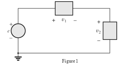
Find the nonsinusoidal expression for the voltage oe of the diagram in Fig. 26.39.
Expert Solution & Answer
Want to see the full answer?
Check out a sample textbook solution
Students have asked these similar questions
I need help creating a graph in Excel for the tables below. It needs to be Vce vs Ic and plots the Ib average for each table. The averages are below. Please show step by step.
V1 = 4V
V2 (V)
Ib (µA)
Ic (mA)
Ie (mA)
Vce (mV)
Beta
0
11.5
-0.00794
-0.00356
7.94
-0.000690434783
1
11.1
0.701
-0.712
299
0.0631531532
2
11.1
0.711
-0.722
1290
0.0640540541
Table 1: V1 = 4, V2= 0-2 V
V1 = 6V
V2 (V)
Ib (µA)
Ic (mA)
Ie (mA)
Vce (mV)
Beta
0
18.1
-0.0105
-0.00761
10.5
-0.000580110497
1
17.8
0.856
-0.874
144
0.0480898876
2
17.8
1.20
-1.22
797
0.0674157303
3
17.8
1.22
-1.25
1780
0.0685393258
Table 2: V1 = 6, V2= 0-3 V
V1 = 8V
V2 (V)
Ib (µA)
Ic (mA)
Ie (mA)
Vce (mV)
Beta
0
24.7
-0.0123
-0.0125
12.3
-0.000497975709
1
24.5
0.878
-0.903
122
0.0358367347
2
24.4
1.71
-1.73
291
0.0700819672
4
24.4…
A voltage wave of 250 kHz has a Vmax-5 V and Vmin=-35 V. The duty cycle of this wave is 0.875.
This voltage waveform has been applied across a 2.5 µH inductor for a very long time so that steady
state has been achieved.
Diagrams of the wave parameters and circuit are shown in this figure:
L
What is the average voltage of this wave?
Average voltage = 35 V
Voltage (arb, unit)
1.25
Minimum current: -3.5€ Amps
1
0.75
0.5
0.25
0
4.25
05
Have you integrated the wave over full cycle?
4.75
4
-1.25
Vmax
0.5
Vmin
What is the average current flowing through the inductor?
Average current = 3.56 A
15
Period/s
On average, there is no power consumed by the inductor. Have you considered this?
What are the maximum and minimum currents that flow through the inductor?
Maximum current: 0.50 Amps
D=
25
TH
TH
Have you used the relationship for current and voltage in an inductor? Have you considered the slope
of the current wave?
Solve for Beta :
www m
Vcc= 12V
VCE= 6V
RB= 470 Kiloohms
Rc= 1500 ohms
RE= 1000 ohms
Chapter 26 Solutions
Laboratory Manual for Introductory Circuit Analysis
Ch. 26 - For the waveforms in Fig. 26.32, determine whether...Ch. 26 - If the Fourier series for the waveform in Fig....Ch. 26 - Prob. 3PCh. 26 - Sketch the following nonsinusoidal waveforms with ...Ch. 26 - Sketch the following nonsinusoidal waveforms with...Ch. 26 - Sketch the Fourier spectrum for the waveforms of...Ch. 26 - Sketch the Fourier spectrum for the waveform of...Ch. 26 - Sketch the Fourier spectrum for the waveform of...Ch. 26 - Find the average and effective values of the...Ch. 26 - Find the rms value of the following nonsinusoidal...
Ch. 26 - Find the total average power to a circuit whose...Ch. 26 - Prob. 12PCh. 26 - The Fourier series representation for the input...Ch. 26 - Prob. 14PCh. 26 - Prob. 15PCh. 26 - Prob. 16PCh. 26 - The input voltage in Fig. 26.36(a) to the circuit...Ch. 26 - Find the Fourier series expression for the voltage...Ch. 26 - Perform the indicated operations on the following...Ch. 26 - Prob. 20PCh. 26 - Find the nonsinusoidal expression for the voltage...Ch. 26 - Plot a half-rectified waveform with a peak value...
Knowledge Booster


Learn more about
Need a deep-dive on the concept behind this application? Look no further. Learn more about this topic, electrical-engineering and related others by exploring similar questions and additional content below.Similar questions
- A 0.33 μF capacitor is charged to 150 VDC. It is then connected to another capacitor of capacitance 4 times the capacitance of it. Find the loss of energy. Select one O a. Not on the list b. 29.71 x 10 J c. 25.14 x 10 d. 29.17 x 10 J e. 39.35 x 10¹arrow_forwardconvert the figure and calculate the magnitude and the angles of Za, Zb and Zcarrow_forwardQ2) If Emin =3V and e. (t)=6sin(2nx105 t), fm =5KHZ, find Emax , Ec , Em , BW. Ptotal and draw the AM waveform for the following cases: 1) m=1.2 2) m=0.25 %3Darrow_forward
- Calibri (Body) -11 by AaBbCcDx AaBbCcD AaBbC AaBbCc AaB AaBbCc. mat Painter BIU 1Normal 1No Spaci. Heading 1 Heading 2 Title Subtitle Chang Styles d Font Paragraph Styles IMPEDANCE QUIZ # 2 1. What capacitance when connected in series with a 500Q resistor will limit the current drawn from a 48-mV 465-kHz source to 20µA? * a. 144pF b. 145pF c. 146pF d. 147pF MY ANSWER: c.146pF 2. What is the total impedance at 20kHz of a series circuit consisting of a 1.5mH inductance, a 100Q resistance, and a 0.08uF capacitance? * a. 1340 41.7 b. 1930 L-37.2" C. 920 290 d. 530 2-12.6°arrow_forwardWhat is the frequency of the input signal if the measured capacitive reactance is equal to 28 Q. Given that R1 = 1738 Q and C1 = 1 micro Farad. The voltage is kept constant at 5V. Note: Express your answer in Hz and in 2 decimal places. No need to include the unit. V R1 www C1 Xc Vout -Oarrow_forwardR=1 ka A Oscilloscope V-5 V f=500 Hz In the given circuit, a sinusoidal signal is applied at the source, current measured by AVO meter is 0.01A (RMS) and voltage measured by oscilloscope is 25mV(peak). What is the capacitance value of capacitor? Lütfen birini seçin: a.1 uF b.0.18 mF c.0.15 mF d.0.1mF e.0.12 mFarrow_forward
- Q/Exprees the de cinaluunber (83)(-85)2 see complenust)arrow_forwardVI Find v₁ and v2 for @= 10000 rad/sec. Sketch the waveforms for vs, vi and v2. Repeat for ( = 100 rad/sec. Zc = jwc DC VDC PR₁ VID² v₁ = 10 cos(cor) V R₂ Rs 10 Ω Rs 1.0 ΚΩ 10.0 μF HH 20 V 1.0 ΚΩ R2 www. R₁ 10.0 μF HH + V₁ 10.0 kn - AC od R. //R₂ www RL +51 _w_111 + RL V₂ Iarrow_forward"If lab is equal to 595.8252306 and lb is 344296, the phase sequence is:" O POSITIVE O NEGATIVEarrow_forward
- A series circuit consisting of a resistor, 0.05 H inductor and a 100-microfarad capacitor is connected across a 100V, 60Hz. Determine the value of the resistor if the phase angle is 80 degrees. Show complete solution and limit your answer into three decimal places.arrow_forwardA current of 1A RMS 60HZ flows through a 120mH inductor. Calculate the RMS voltage drop across the inductor. 25.7V RMS O 45.2V RMS O 33.1V RMS O 18.8V RMSarrow_forwardOne leg of a radio-tuned circuit has a capacitance of one times ten to the minus nine farad. It is tuned at 200kHz, what is the inductance of the other leg in henry?arrow_forward
arrow_back_ios
SEE MORE QUESTIONS
arrow_forward_ios
Recommended textbooks for you
 Introductory Circuit Analysis (13th Edition)Electrical EngineeringISBN:9780133923605Author:Robert L. BoylestadPublisher:PEARSON
 Delmar's Standard Textbook Of ElectricityElectrical EngineeringISBN:9781337900348Author:Stephen L. HermanPublisher:Cengage Learning
 Programmable Logic ControllersElectrical EngineeringISBN:9780073373843Author:Frank D. PetruzellaPublisher:McGraw-Hill Education
 Fundamentals of Electric CircuitsElectrical EngineeringISBN:9780078028229Author:Charles K Alexander, Matthew SadikuPublisher:McGraw-Hill Education
 Electric Circuits. (11th Edition)Electrical EngineeringISBN:9780134746968Author:James W. Nilsson, Susan RiedelPublisher:PEARSON
 Engineering ElectromagneticsElectrical EngineeringISBN:9780078028151Author:Hayt, William H. (william Hart), Jr, BUCK, John A.Publisher:Mcgraw-hill Education,
Introductory Circuit Analysis (13th Edition)
Electrical Engineering
ISBN:9780133923605
Author:Robert L. Boylestad
Publisher:PEARSON
Delmar's Standard Textbook Of Electricity
Electrical Engineering
ISBN:9781337900348
Author:Stephen L. Herman
Publisher:Cengage Learning
Programmable Logic Controllers
Electrical Engineering
ISBN:9780073373843
Author:Frank D. Petruzella
Publisher:McGraw-Hill Education
Fundamentals of Electric Circuits
Electrical Engineering
ISBN:9780078028229
Author:Charles K Alexander, Matthew Sadiku
Publisher:McGraw-Hill Education
Electric Circuits. (11th Edition)
Electrical Engineering
ISBN:9780134746968
Author:James W. Nilsson, Susan Riedel
Publisher:PEARSON
Engineering Electromagnetics
Electrical Engineering
ISBN:9780078028151
Author:Hayt, William H. (william Hart), Jr, BUCK, John A.
Publisher:Mcgraw-hill Education,
Resonance Circuits: LC Inductor-Capacitor Resonating Circuits; Author: Physics Videos by Eugene Khutoryansky;https://www.youtube.com/watch?v=Mq-PF1vo9QA;License: Standard YouTube License, CC-BY