
University Physics with Modern Physics, Volume 2 (Chs. 21-37); Mastering Physics with Pearson eText -- ValuePack Access Card (14th Edition)
14th Edition
ISBN: 9780134265414
Author: Hugh D. Young, Roger A. Freedman
Publisher: PEARSON
expand_more
expand_more
format_list_bulleted
Videos
Textbook Question
Chapter 26, Problem 26.32E
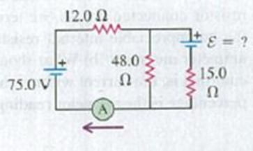
In the circuit shown in Fig. E26.32 both batteries have insignificant internal resistance and the idealized ammeter reads 1.50 A in the direction shown. Find the emf ε of the battery. Is the polarity shown correct?
Figure E26.32
Expert Solution & Answer

Trending nowThis is a popular solution!

Learn your wayIncludes step-by-step video

schedule05:02
Students have asked these similar questions
25.54. In the circuit shown in
Fig. P25.54, R is a variable resistor whose
value ranges from 0 to co, and a and b are
the terminals of a battery that has an emf
E = 15.0V and an internal resistance of
4.00 2. The ammeter and voltmeter are
idealized meters. As R varies over its full
range of values, what will be the largest
and smallest readings of (a) the voltmeter
and (b) the ammeter? (c) Sketch qualita-
tive graphs of the readings of both meters
as functions of R.
Figure P25.54
R
When switch S in Fig. E25.33 is open, the voltmeter V of the battery reads 3.08 V. When the switch is closed, the voltmeter reading drops to 2.97 V, and the ammeter A reads 1.65 A. Find the emf, the internal resistance of the battery, and the circuit resistance R. Assume that the two meters are ideal, so they don’t affect the circuit.
26.29. In the circuit shown in Fig. E26.29 the batteries have neg-
ligible internal resistance and the meters are both idealized. With the
switch S open, the voltmeter reads 17.0 V. (a) Find the emf & of the bat-
tery. (b) What will the ammeter read when the switch is closed?
Figure E26.29
30.0 Ω
www
20.0
75.0
52
25.0 V
50.0
Ω
Ω
ε = ? $1
Chapter 26 Solutions
University Physics with Modern Physics, Volume 2 (Chs. 21-37); Mastering Physics with Pearson eText -- ValuePack Access Card (14th Edition)
Ch. 26.1 - Suppose all three of the resistors shown in Fig....Ch. 26.2 - Subtract Eq. (1) from Eq. (2) in Example 26.6. To...Ch. 26.3 - You want to measure the current through and the...Ch. 26.4 - The energy stored in a capacitor is equal to...Ch. 26.5 - To prevent the circuit breaker in Example 26.14...Ch. 26 - In which 120-V light bulb does the filament have...Ch. 26 - Two 120-V light bulbs, one 25-W and one 200-W,...Ch. 26 - You connect a number of identical light bulbs to a...Ch. 26 - In the circuit shown in Fig. Q26.4, three...Ch. 26 - If two resistors R1 and R2 (R2 R1) are connected...
Ch. 26 - If two resistors R1 and R2 (R2 R1) are connected...Ch. 26 - A battery with no internal resistance is connected...Ch. 26 - A resistor consists of three identical metal...Ch. 26 - A light bulb is connected in the circuit shown in...Ch. 26 - A real battery, having nonnegligible internal...Ch. 26 - If the battery in Discussion Question Q26.10 is...Ch. 26 - Consider the circuit shown in Fig. Q26.12. What...Ch. 26 - Is it possible to connect resistors together in a...Ch. 26 - The battery in the circuit shown in Fig. Q26.14...Ch. 26 - In a two-cell flashlight, the batteries are...Ch. 26 - Identical light bulbs A, B, and C are connected as...Ch. 26 - The emf of a flashlight battery is roughly...Ch. 26 - Will the capacitors in the circuits shown in Fig....Ch. 26 - Verify that the time constant RC has units of...Ch. 26 - For very large resistances it is easy to construct...Ch. 26 - When a capacitor, battery, and resistor are...Ch. 26 - A uniform wire of resistance R is cut into three...Ch. 26 - A machine part has a resistor X protruding from an...Ch. 26 - A resistor with R1 = 25.0 is connected to a...Ch. 26 - A 42- resistor and a 20- resistor are connected in...Ch. 26 - A triangular array of resistors is shown in Fig....Ch. 26 - For the circuit shown in Fig. E26.6 both meters...Ch. 26 - For the circuit shown in Fig. E26.7 find the...Ch. 26 - Three resistors having resistances of 1.60 , 2.40...Ch. 26 - Now the three resistors of Exercise 26.8 are...Ch. 26 - Power Rating of a Resistor. The power rating of a...Ch. 26 - In Fig. E26.11, R1, = 3.00 , R2 = 6.00 , and R3=...Ch. 26 - In Fig. E26.11 the battery has emf 35.0 V and...Ch. 26 - Compute the equivalent resistance of the network...Ch. 26 - Compute the equivalent resistance of the network...Ch. 26 - In the circuit of Fig. E26.15, each resistor...Ch. 26 - Consider the circuit shown in Fig. E26.16. The...Ch. 26 - In the circuit shown in Fig. E26.17, the voltage...Ch. 26 - In the circuit shown in Fig. E26.18, = 36.0 V,...Ch. 26 - CP In the circuit in Fig. E26.19, a 20.0- resistor...Ch. 26 - In the circuit shown in Fig. E26.20, the rate at...Ch. 26 - Light Bulbs in Series and in Parallel. Two light...Ch. 26 - Light Bulbs in Series. A 60-W, 120-V light bulb...Ch. 26 - In the circuit shown in Fig. E26.23, ammeter A1...Ch. 26 - The batteries shown in the circuit in Fig. E26.24...Ch. 26 - In the circuit shown in Fig. E26.25 find (a) the...Ch. 26 - Find the emfs 1 and 2 in the circuit of Fig....Ch. 26 - In the circuit shown in Fig. E26.27, find (a) the...Ch. 26 - In the circuit shown in Fig. E26.28, find (a) the...Ch. 26 - The 10.00-V battery in Fig. E26.28 is removed from...Ch. 26 - The 5.00-V battery in Fig. E26.28 is removed from...Ch. 26 - In the circuit shown in Fig. E26.31 the batteries...Ch. 26 - In the circuit shown in Fig. E26.32 both batteries...Ch. 26 - In the circuit shown in Fig. E26.33 all meters are...Ch. 26 - In the circuit shown in Fig. E26.34, the 6.0-...Ch. 26 - The resistance of a galvanometer coil is 25.0 ,...Ch. 26 - The resistance of the coil of a pivoted coil...Ch. 26 - A circuit consists of a series combination of...Ch. 26 - A galvanometer having a resistance of 25.0 has a...Ch. 26 - A capacitor is charged to a potential of 12.0 V...Ch. 26 - You connect a battery, resistor, and capacitor as...Ch. 26 - A 4.60-F capacitor that is initially uncharged is...Ch. 26 - You connect a battery, resistor, and capacitor as...Ch. 26 - CP In the circuit shown in Fig. E26.43 both...Ch. 26 - A 12.4-F capacitor is connected through a 0.895-M...Ch. 26 - An emf source with = 120 V, a resistor with R =...Ch. 26 - A resistor and a capacitor are connected in series...Ch. 26 - CP In the circuit shown in Fig. E26.47 each...Ch. 26 - A 1.50-F capacitor is charging through a 12.0-...Ch. 26 - In the circuit in Fig. E26.49 the capacitors are...Ch. 26 - A 12.0-F capacitor is charged to a potential of...Ch. 26 - In the circuit shown in Fig. E26.51, C = 5.90 F, ...Ch. 26 - Prob. 26.52ECh. 26 - A 1500-W electric beater is plugged into the...Ch. 26 - In Fig. P26.54, the battery has negligible...Ch. 26 - The two identical light bulbs in Example 26.2...Ch. 26 - Each of the three resistors in Fig. P26.56 has a...Ch. 26 - (a) Find the potential of point a with respect to...Ch. 26 - CP For the circuit shown in Fig. P26.58 a 20.0-...Ch. 26 - Calculate the three currents I1, I2, and I3...Ch. 26 - What must the emf in Fig. P26.60 be in order for...Ch. 26 - Find the current through each of the three...Ch. 26 - (a) Find the current through the battery and each...Ch. 26 - Consider the circuit shown in Fig. P26.63. (a)...Ch. 26 - In the circuit shown in Fig. P26.64, = 24.0 V,...Ch. 26 - In the circuit shown in Fig. P26.65, the current...Ch. 26 - In the circuit shown in Fig. P26.66 all the...Ch. 26 - Figure P26.67 employs a convention often used in...Ch. 26 - Three identical resistors are connected in series....Ch. 26 - A resistor R1 consumes electrical power P1 when...Ch. 26 - The capacitor in Fig. F26.70 is initially...Ch. 26 - A 2.00-F capacitor that is initially uncharged is...Ch. 26 - A 6.00-F capacitor that is initially uncharged is...Ch. 26 - Point a in Fig. P26.73 is maintained at a constant...Ch. 26 - The Wheatstone Bridge. The circuit shown in Fig....Ch. 26 - (See Problem 26.67.) (a) What is the potential of...Ch. 26 - A 2.36-F capacitor that is initially uncharged is...Ch. 26 - A 224- resistor and a 589- resistor are connected...Ch. 26 - A resistor with R = 850 is connected to the...Ch. 26 - A capacitor that is initially uncharged is...Ch. 26 - DATA You set up the circuit shown in Fig. 26.22a,...Ch. 26 - DATA You set up the circuit shown in Fig. 26.20....Ch. 26 - DATA The electronics supply company where you work...Ch. 26 - An Infinite Network. As shown in Fig. P26.83, a...Ch. 26 - Suppose a resistor R lies along each edge of a...Ch. 26 - BIO Attenuator Chains and Axons. The infinite...Ch. 26 - Assume that a typical open ion channel spanning an...Ch. 26 - In a simple model of an axon conducting a nerve...Ch. 26 - Cell membranes across a wide variety of organisms...
Additional Science Textbook Solutions
Find more solutions based on key concepts
The formula for the half-life can be expressed as A=A0(1/2)t/h where A0 is initial amount, A is final amount, t...
Conceptual Integrated Science
14. For Questions 12 through 17, give a specific example of a process that has the energy changes and transfers...
College Physics: A Strategic Approach (4th Edition)
In the circuit shown in Fig. 24–37. C1 = 1.0 μF, C2 = 2.0 μF. C3 = 2.4 μF, and a voltage Vab = 24 V is applied ...
Physics for Scientists and Engineers with Modern Physics
The magnitude and direction of ball’s velocity at 0.250 s .
Physics (5th Edition)
Dielectric breakdown of air occurs at fields of 3 MV/m. Find (a) the maximum potential (measured from infinity)...
Essential University Physics (3rd Edition)
Explain all answers clearly, with complete sentences and proper essay structure if needed. An asterisk (*) desi...
The Cosmic Perspective Fundamentals (2nd Edition)
Knowledge Booster


Learn more about
Need a deep-dive on the concept behind this application? Look no further. Learn more about this topic, physics and related others by exploring similar questions and additional content below.Similar questions
- A 400 µF capacitor is connected through a resistor to a battery. Find (a) the resistance R and (b) the emf of the battery if the time constant of the circuit is 0.5 s and the maximum charge on the capacitor is 0.024 C. O a. R = 1350 0, e = 80 V O b. R = 1250 0, E = 60 V O C. R = 1200 Q, e = 80 V O d. R = 1150 Q, e = 60 Varrow_forwardTwo resistors, R1 = 21 Ω and R2 = 35 Ω are connected in parallel across a battery providing voltage ΔVbat = 5.7 V. What is the current through resistor R1?arrow_forwardA heart pacemaker fires exactly 71 times a minute. Each time it fires, a 19.0 nF capacitor is charged by a battery in series with a resistor to 0.582 of its full voltage. What is the value of the resistance R?arrow_forward
- In the circuit, R= 30.0 kN and C = 0.100 µF. The capacitor is allowed to charge fully, and then the switch is changed from position a to position b. What will the voltage across the resistor be 8.40 ms later? R where X = 64.1 V.arrow_forwardA capacitor charging circuit consists of a battery, an uncharged 20 μF capacitor, and a 5.6 kΩkΩ resistor. At t = 0 ss the switch is closed; 0.15 s later, the current is 0.46 mA . What is the battery's emf?arrow_forward24.0 V 4.00 A R 4.00 A Figure N 8. Consider the circuit shown in Figure b. The terminal voltage of the 24.0 V battery is 21.2 V. What is a) the internal resistance r of the battery; b) the resistance R of the circuit resistor???arrow_forward
- 26.11 In Fig. E26.11, R₁ = 3.00, R₂ = 6.00 , and R3 = 5.00 2. The battery has negligible internal resistance. The current 1₂ through R₂ is 4.00 A. (a) What are the currents I₁ and 13? (b) What is the emf of the battery? Figure E26.11 R₁ R₂ www R3arrow_forwardThe 10.00-V batteryin Fig. E26.28 is removedfrom the circuit and reinsertedwith the opposite polarity, sothat its positive terminal is now next to point a. The rest of the circuit is as shown in the figure. Find (a) the current in each branchand (b) the potential difference of point a relative to point barrow_forwardA charging RC circuit controls the intermittent windshield wipers in a car. The emf is 12.0 V. The wipers are triggered when the voltage across the 110 μF capacitor reaches 10.0 V; then the capacitor is quickly discharged (through a much smaller resistor) and the cycle repeats. What resistance should be used in the charging circuit if the wipers are to operate once every 1.40 s?arrow_forward
- The circuit in Figure P28.53 has been connected for several seconds. Find the current (a) in the 4.00-V battery, (b) in the 3.00-Ω resistor, (c) in the 8.00-V battery, and (d) in the 3.00-V battery. (e) Find the charge on the capacitor.arrow_forwardFigure E26.26 2.00 210.00 V a ww 1.00 2 5.00 V www 10.00 Ω ww 26.27 The 10.00 V battery in Fig. E26.26 is removed from the cir- cuit and reinserted with the opposite polarity, so that its positive ter- minal is now next to point a. The rest of the circuit is as shown in the figure. Find (a) the current in each branch and (b) the potential differ- ence Van of point a relative to point b. 3.00 Ω 4.00 Ω barrow_forwardA 1000. µ F uncharged capacitor is connected in series with a 2.00KN resistor. The capacitor will be charged using a 5 V battery such that the whole circuit is connected in series. At t = 0, the switch is closed. What will be the charge when t = 1.5T? О А. 1.12шС оВ. 3.88 mC ос. 3.88дС O D. 1.12 mCarrow_forward
arrow_back_ios
SEE MORE QUESTIONS
arrow_forward_ios
Recommended textbooks for you
 Physics for Scientists and Engineers: Foundations...PhysicsISBN:9781133939146Author:Katz, Debora M.Publisher:Cengage Learning
Physics for Scientists and Engineers: Foundations...
Physics
ISBN:9781133939146
Author:Katz, Debora M.
Publisher:Cengage Learning
How To Solve Any Resistors In Series and Parallel Combination Circuit Problems in Physics; Author: The Organic Chemistry Tutor;https://www.youtube.com/watch?v=eFlJy0cPbsY;License: Standard YouTube License, CC-BY