
EP PHYSICS F/SCI.+ENGR.W/MOD..-MOD MAST
4th Edition
ISBN: 9780133899634
Author: GIANCOLI
Publisher: PEARSON CO
expand_more
expand_more
format_list_bulleted
Videos
Textbook Question
Chapter 26, Problem 76GP
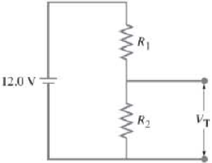
A power supply has a fixed output voltage of 12.0 V, but you need VT = 3.0 V output for an experiment. (a) Using the voltage divider shown in Fig. 26–66, what should R2 be if R1 is 14.5 Ω? (b) What will the terminal voltage VT be if you connect a load to the 3.0-V output, assuming the load has a resistance of 7.0 Ω?
FIGURE 26–66 Problem 76.
Expert Solution & Answer
Want to see the full answer?
Check out a sample textbook solution
Students have asked these similar questions
A three-way lightbulb can produce 50 W, 100 W, or 150 W,
at 120 V. Such a bulb contains two filaments that can be
connected to the 120 V individually or in parallel (Fig. 19–74).
(a) Describe how the
connections to the
two filaments are
made to give each of
the three wattages.
(b) What must be the
resistance of each
filament?
FIGURE 19–74
Problem 68.
Te-Learning Portal
Courses -
Reports
e-Services ▼
Academic Departments -
ETC -
CIMS
Salim
During an experiment to verify Ohm's law, the voltage supplied and the current through a circuit are measured.
[Voltage is measured in Volt (V) and current in Ampere (A)].
ww
R
on
Battery
The measured value of the current is I = 3.1 ± 0.2 A and that of the voltage is V = 14 0.5 V. The resistance of
the circuit (in N) can be calculated using the formula, R = V/I,
Calculate the,
a) Resistance (in 2) =
b) Fractional uncertainty in the resistance =
c) Absolute uncertainty (in 2) in the resistance=
(II) Eight identical bulbs are connected in series across a120-V line. (a) What is the voltage across each bulb? (b) Ifthe current is 0.45 A, what is the resistance of each bulb,and what is the power dissipated in each?
Chapter 26 Solutions
EP PHYSICS F/SCI.+ENGR.W/MOD..-MOD MAST
Ch. 26.1 - Repeat Example 261 assuming now that the...Ch. 26.2 - You have a 10- and a 15- resistor. What is the...Ch. 26.3 - Write the equation for the lower loop abcdefga of...Ch. 26.4 - If the jumper cables of Example 2610 were...Ch. 26.5 - In 10 times constants, the charge on the capacitor...Ch. 26 - Explain why birds can sit on power lines safely,...Ch. 26 - Discuss the advantages and disadvantages of...Ch. 26 - If all you have is a 120-V line, would it be...Ch. 26 - Two lightbulbs of resistance R1 and R2 (R2 R1)...Ch. 26 - Household outlets are often double outlets. Are...
Ch. 26 - With two identical lightbulbs and two identical...Ch. 26 - If two identical resistors are connected in series...Ch. 26 - You have a single 60-W bulb on in your room. How...Ch. 26 - When applying Kirchhoffs loop rule (such as in...Ch. 26 - Compare and discuss the formulas for resistors and...Ch. 26 - For what use are batteries connected in series?...Ch. 26 - Can the terminal voltage of a battery ever exceed...Ch. 26 - Explain in detail how you could measure the...Ch. 26 - In an RC circuit, current flows from the battery...Ch. 26 - Given the circuit shown in Fig. 2634, use the...Ch. 26 - Figure 2635 is a diagram of a capacitor (or...Ch. 26 - Design a circuit in which two different switches...Ch. 26 - What is the main difference between an analog...Ch. 26 - What would happen if you mistakenly used an...Ch. 26 - Explain why an ideal ammeter would have zero...Ch. 26 - A voltmeter connected across a resistor always...Ch. 26 - A small battery-operated flashlight requires a...Ch. 26 - Different lamps might have batteries connected in...Ch. 26 - Prob. 1PCh. 26 - (I) Four 1.50-V cells are connected in series to a...Ch. 26 - (II) A 1.5-V dry cell can be tested by connecting...Ch. 26 - (II) What is the internal resistance of a 12.0-V...Ch. 26 - (I) A 650- and a 2200- resistor are connected in...Ch. 26 - (I) Three 45- lightbulbs and three 65- lightbulbs...Ch. 26 - (I) Suppose that you have a 680-, a 720-, and a...Ch. 26 - (I) How many 10- resistors must be connected in...Ch. 26 - (II) Suppose that you have a 9.0-V battery and you...Ch. 26 - Three 1.70-k resistors can be connected together...Ch. 26 - (II) A battery with an emf of 12.0 V shows a...Ch. 26 - (II) Eight identical bulbs are connected in series...Ch. 26 - (II) Eight bulbs are connected in parallel to a...Ch. 26 - (II) The performance of the starter circuit in an...Ch. 26 - (II) A close inspection of an electric circuit...Ch. 26 - (II) Determine (a) the equivalent resistance of...Ch. 26 - (II) A 75-W, 110-V bulb is connected in parallel...Ch. 26 - (II) (a) Determine the equivalent resistance of...Ch. 26 - (II) Whal is the net resistance of the circuit...Ch. 26 - (II) Calculate the current through each resistor...Ch. 26 - (II) The two terminals of a voltage source with...Ch. 26 - (II) Two resistors when connected in series to a...Ch. 26 - (III) Three equal resistors (R) are connected to a...Ch. 26 - (III) A 2.8-k and a 3.7-k resistor are connected...Ch. 26 - (III) Consider the network of resistors shown in...Ch. 26 - (III) You are designing a wire resistance heater...Ch. 26 - (I) Calculate the current in the circuit of Fig....Ch. 26 - (II) Determine the terminal voltage of each...Ch. 26 - (II) For the circuit shown in Fig. 2647, find the...Ch. 26 - (II) (a) A network of five equal resistors R is...Ch. 26 - (II) (a) What is the potential difference between...Ch. 26 - (II) Calculate the currents in each resistor of...Ch. 26 - (II) Determine the magnitudes and directions of...Ch. 26 - (II) Determine the magnitudes and directions of...Ch. 26 - (II) A voltage V is applied to n identical...Ch. 26 - (III) (a) Determine the currents I1, I2, and I3 in...Ch. 26 - (III) What would the current I1 be in Fig. 2653 if...Ch. 26 - (III) Determine the current through each of the...Ch. 26 - (III) If the 25- resistor in Fig. 2654 is shorted...Ch. 26 - (III) Twelve resistors, each of resistance R, are...Ch. 26 - (III) Determine the net resistance in Fig. 2656...Ch. 26 - (II) Suppose two batteries, with unequal emfs of...Ch. 26 - (I) Estimate the range of resistance needed to...Ch. 26 - (II) In Fig. 2658 (same as Fig. 2617a), the total...Ch. 26 - (II) Two 3.8-F capacitors, two 2.2-k resistors,...Ch. 26 - (II) How long does it take for the energy stored...Ch. 26 - (II) A parallel-plate capacitor is filled with a...Ch. 26 - (II) The RC circuit of Fig. 2659 (same as Fig....Ch. 26 - (II) Consider the circuit shown in Fig. 2660,...Ch. 26 - (III) Determine the time constant for charging the...Ch. 26 - (III) Two resistors and two uncharged capacitors...Ch. 26 - (III) Suppose the switch S in Fig. 2662 is closed....Ch. 26 - (I) An ammeter has a sensitivity of 35,00 /V. What...Ch. 26 - (I) What is the resistance of a voltmeter on the...Ch. 26 - (II) A galvanometer has a sensitivity of 45 k/V...Ch. 26 - (II) A galvanometer has an internal resistance of...Ch. 26 - (II) A particular digital meter is based on an...Ch. 26 - (II) A milliammeter reads 25 mA full scale. It...Ch. 26 - (II) A 45-V battery of negligible internal...Ch. 26 - (II) An ammeter whose internal resistance is 53 ...Ch. 26 - (II) A battery with E=12.0V and internal...Ch. 26 - (II) A 12.0-V battery (assume the internal...Ch. 26 - (III) Two 9.4-k resistors are placed in series and...Ch. 26 - (III) When the resistor R in Fig. 2664 is 35 , the...Ch. 26 - Suppose that you wish to apply a 0.25-V potential...Ch. 26 - A three-way lightbulb can produce 50 W, 100 W, or...Ch. 26 - Suppose you want to run some apparatus that is 65...Ch. 26 - For the circuit shown in Fig. 2618a, show that the...Ch. 26 - A heart pacemaker is designed to operate at 72...Ch. 26 - Prob. 70GPCh. 26 - A Wheatstone bridge is a type of bridge circuit...Ch. 26 - An unknown length of platinum wire 1.22 mm in...Ch. 26 - The internal resistance of a 1.35-V mercury cell...Ch. 26 - How many 12-W resistors, each of the same...Ch. 26 - A solar cell, 3.0 cm square, has an output of 350...Ch. 26 - A power supply has a fixed output voltage of 12.0...Ch. 26 - The current through the 4.0-k resistor in Fig....Ch. 26 - A battery produces 40.8 V when 7.40 A is drawn...Ch. 26 - In the circuit shown in Fig. 2668, the 33-...Ch. 26 - The current through the 20- resistor in Fig. 2669...Ch. 26 - (a) A voltmeter and an ammeter can be connected as...Ch. 26 - (a) What is the equivalent resistance of the...Ch. 26 - A flashlight bulb rated at 2.0 W and 3.0 V is...Ch. 26 - Some light-dimmer switches use a variable resistor...Ch. 26 - A potentiometer is a device to precisely measure...Ch. 26 - Electronic devices often use an RC circuit to...Ch. 26 - The circuit shown in Fig. 2676 is a primitive...Ch. 26 - Determine the current in each resistor of the...Ch. 26 - In the circuit shown in Fig. 2678, switch S is...Ch. 26 - Figure 2679 shows the circuit for a simple...Ch. 26 - Measurements made on circuits that contain large...Ch. 26 - A typical voltmeter has an internal resistance of...Ch. 26 - (II) An RC series circuit contains a resistor R =...
Additional Science Textbook Solutions
Find more solutions based on key concepts
Using the definitions in Eqs. 1.1 and 1.4, and appropriate diagrams, show that the dot product and cross produc...
Introduction to Electrodynamics
Plate Tectonics. Typical motions of one plate relative to another are 2 centimeters per year. At this rate, how...
Life in the Universe (4th Edition)
64. The ultracentrifuge is an important tool for separating and analyzing proteins in biological research. Beca...
College Physics: A Strategic Approach (3rd Edition)
Would you say the temperature stays approximately the same every month of the year at your location?
Lecture- Tutorials for Introductory Astronomy
Choose the BEST way to complete the statement.
1. The source of all magnetism is
(a) tiny bits of iron.
(b) tin...
Conceptual Physical Science (6th Edition)
Knowledge Booster


Learn more about
Need a deep-dive on the concept behind this application? Look no further. Learn more about this topic, physics and related others by exploring similar questions and additional content below.Similar questions
- 15 - In the circuit shown in the figure, the ammeter and voltmeter are ideal. If e = 4V, R = 9N and r = 1N, then readings of ammeter and voltmeter are... V R R wwww ww E,r A a) 1 А, 4V b) 2 А, 3 V c) O A, 4 V d) 1 А, ЗV e) 4 А, 4 V Boş bırakarrow_forwardA power supply has a fixed output voltage of 12.0 V, but you need Vr = 3.5 V output for an experiment. (a) Using the voltage divider shown in Fig. 19–78, what should R, be if R is 14.5 N? (b) What will the terminal voltage Vr be if you connect a load to the 3.5-V output, assuming the load has a resistance of 7.0 N? R1 12.0 V R2 VT FIGURE 19–78 Problem 79.arrow_forward4) Based on the circuit to the right answer the folowing questbons, SHOW ALL WORK ourrent flows h STEADY STATE (a) The equivalent capacitance and resistance is 20uF c2 (1) (11) () (iv) 26ul, 19kn 5.0uF, 6.0kn 2 5.F. 3 Oko 12V R1 15uF, 14k) 30arrow_forward
- -37 In Fig. 27-48, the resistances are R, = 2.00 N, R, = 5.00 N, and the battery is ideal. What value of R3 Ra R3 maximizes the dissipation rate in resistance 3? wwarrow_forward(III) (a) Determine the currents I, 1,, and Iz in Fig. 19–61. Assume the internal resistance of each battery is r = 1.0 N. (b) What is the terminal voltage of the 6.0-V battery? 12.0 V 22 Ω 12 2 28 Ω |12.0 V 11Ω 16 2 FIGURE 19–61 Problems 34 and 35. 6.0 V I3 wwarrow_forward(I) Calculate the current in the circuit of Fig. 19–53, and show that the sum of all the r= 2.0 2 voltage changes around the circuit is zero. 9.0 V 9.5 Q FIGURE 19–53 Problem 25. 14.0 2arrow_forward
- (III) When the resistor R in Fig. 19-73 is 35 N, the high- resistance voltmeter reads 9.7 V. When R is replaced by a 14.0-N resistor, the voltmeter reading drops to 8.1 V. What are the emf and V internal resistance of the battery? ww R FIGURE 19–73 Problem 66.arrow_forwardGiven the circuit shown in Fig. 19–38, use the words "increases," "decreases," or "stays the same" to complete the following statements: (a) If R, increases, the potential difference between A and - Assume no resistance in O and E. (b) If R, increases, the potential difference between A and Assume O and E have resistance. E E (c) If R, increases, the voltage drop across R4 (d) If R2 decreases, the current through R1 (e) If R, decreases, the current through R6 (f) If R2 decreases, the current through R3 (g) If R5 increases, the voltage drop across R2 (h) If R5 increases, the voltage drop across R4 (i) If R2, R5, and R7 increase, E (r = 0) R4 R5 D R6 R2 R3 R7 В FIGURE 19-38 Question 16. R1 R2, R5, and R, are variable resistors (you can change their resistance), given the symbol -WW-. A Aarrow_forward(II) Suppose two batteries, with unequal emfs of 2.00 V and 3.00 V, are connected as shown in Fig. 19–62. If each internal resistance is r = 0.350 N, and R = 4.00 N, what is the voltage R= 4.00 2 E= 2.00 V across the resistor R? FIGURE 19–62 Problem 36. E = 3.00 v"arrow_forward
- (II) What is the total amount of energy stored in a 12-V, 65 A.Hcar battery when it is fully charged?arrow_forward(II) A 4.5-V battery is connected to a bulb whose resistanceis 1.3 Ω How many electrons leave the battery per minute?arrow_forward(II) A battery with an emf of 12.0 V shows a terminal voltageof 11.8 V when operating in a circuit with two lightbulbs,each rated at 4.0 W (at 12.0 V), which are connected inparallel. What is the battery’s internal resistance?arrow_forward
arrow_back_ios
SEE MORE QUESTIONS
arrow_forward_ios
Recommended textbooks for you
 College PhysicsPhysicsISBN:9781305952300Author:Raymond A. Serway, Chris VuillePublisher:Cengage Learning
 University Physics (14th Edition)PhysicsISBN:9780133969290Author:Hugh D. Young, Roger A. FreedmanPublisher:PEARSON
 Introduction To Quantum MechanicsPhysicsISBN:9781107189638Author:Griffiths, David J., Schroeter, Darrell F.Publisher:Cambridge University Press
 Physics for Scientists and EngineersPhysicsISBN:9781337553278Author:Raymond A. Serway, John W. JewettPublisher:Cengage Learning
 Lecture- Tutorials for Introductory AstronomyPhysicsISBN:9780321820464Author:Edward E. Prather, Tim P. Slater, Jeff P. Adams, Gina BrissendenPublisher:Addison-Wesley
 College Physics: A Strategic Approach (4th Editio...PhysicsISBN:9780134609034Author:Randall D. Knight (Professor Emeritus), Brian Jones, Stuart FieldPublisher:PEARSON
College Physics
Physics
ISBN:9781305952300
Author:Raymond A. Serway, Chris Vuille
Publisher:Cengage Learning
University Physics (14th Edition)
Physics
ISBN:9780133969290
Author:Hugh D. Young, Roger A. Freedman
Publisher:PEARSON
Introduction To Quantum Mechanics
Physics
ISBN:9781107189638
Author:Griffiths, David J., Schroeter, Darrell F.
Publisher:Cambridge University Press
Physics for Scientists and Engineers
Physics
ISBN:9781337553278
Author:Raymond A. Serway, John W. Jewett
Publisher:Cengage Learning
Lecture- Tutorials for Introductory Astronomy
Physics
ISBN:9780321820464
Author:Edward E. Prather, Tim P. Slater, Jeff P. Adams, Gina Brissenden
Publisher:Addison-Wesley
College Physics: A Strategic Approach (4th Editio...
Physics
ISBN:9780134609034
Author:Randall D. Knight (Professor Emeritus), Brian Jones, Stuart Field
Publisher:PEARSON
How To Solve Any Resistors In Series and Parallel Combination Circuit Problems in Physics; Author: The Organic Chemistry Tutor;https://www.youtube.com/watch?v=eFlJy0cPbsY;License: Standard YouTube License, CC-BY