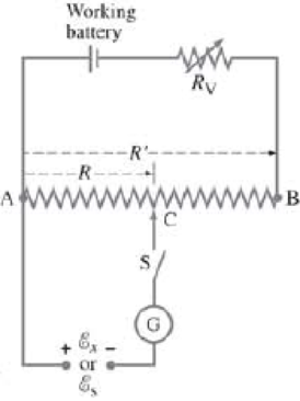
A potentiometer is a device to precisely measure potential differences or emf, using a “null” technique. In the simple potentiometer circuit shown in Fig. 26–74. R ′ represents the total resistance of the resistor from A to B (which could be a long uniform “slide” wire), whereas R represents the resistance of only the part from A to the movable contact at C. When the unknown emf to be measured, E x placed into the circuit as shown, the movable contact C is moved until the galvanometer G gives a null reading (i.e., zero) when the switch S is closed. The resistance between A and C for this situation we call R x . Next, a standard emf, E s , which is known precisely, is inserted into the circuit in place of E x and again the contact C is moved until zero current flows through the galvanometer when the switch S is closed. The resistance between A and C now is called R s . ( a ) Show that the unknown emf is given by E x = ( R x R s ) E s where R x , R s , and E s are all precisely known. The working battery is assumed to be fresh and to give a constant voltage. ( b ) A slide-wire potentiometer is balanced against a 1.0182-V standard cell when the slide wire is set at 33.6 cm out of a total length of 100.0 cm. For an unknown source, the setting is 45.8 cm. What is the emf of the unknown? ( c ) The galvanometer of a potentiometer has an internal resistance of 35 Ω and can detect a current as small as 0.012 mA. What is the minimum uncertainty possible in measuring an unknown voltage? ( d ) Explain the advantage of using this “null” method of measuring emf. FIGURE 26–74 Potentiometer circuit. Problem 85.
A potentiometer is a device to precisely measure potential differences or emf, using a “null” technique. In the simple potentiometer circuit shown in Fig. 26–74. R ′ represents the total resistance of the resistor from A to B (which could be a long uniform “slide” wire), whereas R represents the resistance of only the part from A to the movable contact at C. When the unknown emf to be measured, E x placed into the circuit as shown, the movable contact C is moved until the galvanometer G gives a null reading (i.e., zero) when the switch S is closed. The resistance between A and C for this situation we call R x . Next, a standard emf, E s , which is known precisely, is inserted into the circuit in place of E x and again the contact C is moved until zero current flows through the galvanometer when the switch S is closed. The resistance between A and C now is called R s . ( a ) Show that the unknown emf is given by E x = ( R x R s ) E s where R x , R s , and E s are all precisely known. The working battery is assumed to be fresh and to give a constant voltage. ( b ) A slide-wire potentiometer is balanced against a 1.0182-V standard cell when the slide wire is set at 33.6 cm out of a total length of 100.0 cm. For an unknown source, the setting is 45.8 cm. What is the emf of the unknown? ( c ) The galvanometer of a potentiometer has an internal resistance of 35 Ω and can detect a current as small as 0.012 mA. What is the minimum uncertainty possible in measuring an unknown voltage? ( d ) Explain the advantage of using this “null” method of measuring emf. FIGURE 26–74 Potentiometer circuit. Problem 85.
A potentiometer is a device to precisely measure potential differences or emf, using a “null” technique. In the simple potentiometer circuit shown in Fig. 26–74. R′ represents the total resistance of the resistor from A to B (which could be a long uniform “slide” wire), whereas R represents the resistance of only the part from A to the movable contact at C. When the unknown emf to be measured,
E
x
placed into the circuit as shown, the movable contact C is moved until the galvanometer G gives a null reading (i.e., zero) when the switch S is closed. The resistance between A and C for this situation we call Rx. Next, a standard emf,
E
s
, which is known precisely, is inserted into the circuit in place of
E
x
and again the contact C is moved until zero current flows through the galvanometer when the switch S is closed. The resistance between A and C now is called Rs. (a) Show that the unknown emf is given by
E
x
=
(
R
x
R
s
)
E
s
where Rx, Rs, and
E
s
are all precisely known. The working battery is assumed to be fresh and to give a constant voltage. (b) A slide-wire potentiometer is balanced against a 1.0182-V standard cell when the slide wire is set at 33.6 cm out of a total length of 100.0 cm. For an unknown source, the setting is 45.8 cm. What is the emf of the unknown? (c) The galvanometer of a potentiometer has an internal resistance of 35 Ω and can detect a current as small as 0.012 mA. What is the minimum uncertainty possible in measuring an unknown voltage? (d) Explain the advantage of using this “null” method of measuring emf.
For the circuit shown in Fig.a 20.0 Ω resistor is embedded in a large block of ice at 0.00°C, and the battery has negligible internal resistance. At what rate (in g /s) is this circuit melting the ice?
When the switch shown in Fig. 19–45 is closed, what willhappen to the voltage across resistor R1 It will(a) increase. (b) decrease. (c) stay the same
Can a copper wire and an aluminum wire of the samelength have the same resistance? Explain
Chapter 26 Solutions
Physics for Science and Engineering With Modern Physics, VI - Student Study Guide
Need a deep-dive on the concept behind this application? Look no further. Learn more about this topic, physics and related others by exploring similar questions and additional content below.
How To Solve Any Resistors In Series and Parallel Combination Circuit Problems in Physics; Author: The Organic Chemistry Tutor;https://www.youtube.com/watch?v=eFlJy0cPbsY;License: Standard YouTube License, CC-BY