Videos
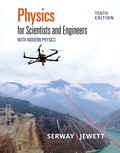
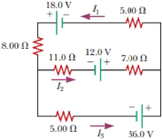
For the circuit shown in Figure P27.22, we wish to find the currents I1, I2, and I3. Use Kirchhoff’s rules to obtain equations for (a) the upper loop, (b) the lower loop, and (c) the junction on the left side. In each case, suppress units for clarity and simplify, combining the terms. (d) Solve the junction equation for I3. (e) Using the equation found in part (d), eliminate I3 from the equation found in part (b). (f) Solve the equations found in parts (a) and (e) simultaneously for the two unknowns I1 and I2. (g) Substitute the answers found in part (f) into the junction equation found in part (d), solving for I3. (h) What is the significance of the negative answer for I2?
Figure P27.22
(a)
The equation by using Kirchhoff’s rules in the upper loop.
Answer to Problem 22P
The equation by using Kirchhoff’s rules in the upper loop is
Explanation of Solution
Given info: The figure is given as,
By going counterclockwise around the upper loop and suppressing the unites, the Kirchhoff’s law is applied.
The equation for the upper loop is,
Conclusion:
Therefore, the equation by using Kirchhoff’s rules in the upper loop is
(b)
The equation by using Kirchhoff’s rules in the lower loop.
Answer to Problem 22P
The equation by using Kirchhoff’s rules in the lower loop is
Explanation of Solution
Given info: The figure is given as,

By going counterclockwise around the lower loop and suppressing the unites, the Kirchhoff’s law is applied.
The equation for the lower loop is,
Conclusion:
Therefore, the equation by using Kirchhoff’s rules in the lower loop is
(c)
The equation by using Kirchhoff’s rules at the junction on the left side.
Answer to Problem 22P
The equation by using Kirchhoff’s rules at the junction on the left side is
Explanation of Solution
Given info: The figure is given as,

Apply the junction rule at the node in the left end of the circuit.
The equation for the junction on the left side is,
Conclusion:
Therefore, the equation by using Kirchhoff’s rules at the junction on the left side is
(d)
To solve: The junction on the left side for
Answer to Problem 22P
The junction on the left side for
Explanation of Solution
Given info: The figure is given as,

Apply the junction rule at the node in the left end of the circuit.
Rearrange the equation (3) as,
Conclusion:
Therefore, the junction on the left side for
(e)
To eliminate: The current
Answer to Problem 22P
The equation after elimination\ for
Explanation of Solution
Given info: The figure is given as,
The equation for
Substitute
Conclusion:
Therefore, the equation after elimination for
(f)
The value of
Answer to Problem 22P
The value of
Explanation of Solution
Given info: The figure is given as,

Rearrange the equation (4) for
Recall the equation (1).
Substitute
Further, solve,
Thus, the value of
Substitute
Conclusion:
Therefore, the value of
(g)
The value of
Answer to Problem 22P
The value of
Explanation of Solution
Given info: The figure is given as,
The equation for
Substitute
Conclusion:
Therefore, the value of
(h)
The significant of the negative sign of answer of
Answer to Problem 22P
The negative sign in the answer for
Explanation of Solution
Given info: The figure is given as,
The negative sign in the answer for
Conclusion:
Therefore, the negative sign in the answer for
Want to see more full solutions like this?
Chapter 27 Solutions
Physics for Scientists and Engineers with Modern Physics
Additional Science Textbook Solutions
University Physics (14th Edition)
Sears And Zemansky's University Physics With Modern Physics
Physics for Scientists and Engineers: A Strategic Approach, Vol. 1 (Chs 1-21) (4th Edition)
University Physics Volume 3
Fundamentals Of Thermodynamics
Schaum's Outline of College Physics, Twelfth Edition (Schaum's Outlines)


- Apply Kirchoff's law to the circuit and write down the linearly independent voltage equations. You must draw the diagram and show the direction of currents in each of the components. The emf's in the circuit have the values E1=4V and E2=12V. The resistors have the following value of resistances R1=2.2Ω, R2=22Ω, R3=4.4Ω, and R4=3.3Ω. b) Find the current through the resistance R3. c) Find the magnitude of potential difference across the points p and q (i.e. potential difference of point q relative to point p. ).arrow_forwardGive the symbolic expression for the emf E using KVL for the circuit with S1 closed and S2 open. Give your answer in terms of the current I, resistor R, capacitors C1 and C2 and charges stored in the respective capacitors Q1 and Q2. Use * to denote product and / to denote division. So to group the product of, say, a and b_1 write a*b_1. And to write a ratio of say, c_1 and d write c_1/d. To add the product and ratio write a*b_1 + c_1/d . a)Write the mathematical expression for emf E. E= In the figure there's a circuit with an emf E=21V, two resistors R1=35kΩ and R2=5.5kΩ, two capacitors C1=25μF and C2=22μF and two switches S1 and S2. b) Find the time constant for this configuration of the circuit. Time constant τ c) Find how much charge will be stored in C2 after time t=1.3τ seconds. Charge stored in C2 PartII After t=10τ seconds, we open switch S1 and close switch S2. Mark current time as t′=0. In this configuration, capacitor C2 discharges through the resistor R2. d) Find…arrow_forwardProblem 3: Consider a circuit shown in the figure. Ignore the internal resistances of the batteries. ℰ1 = 34 Vℰ2 = 46 VR1 = 10 ΩR2 = 4 ΩR3 = 8 Ω. 1. Write the equation of potential change in loop DCAF in terms of the circuit elements. 2. Solve the three equations to get I3. 3. Calculate the numerical value of I3 in A. 4. Calculate the numerical value of I2 in A. 5. Calculate the numerical value of I1 in A.arrow_forward
- For the circuit shown, we wish to find the currents I1, I2, and I3. Use Kirchhoff’s rules to obtain equations for (a) the upper loop, (b) the lower loop, and (c) the junction on the left side. In each case, suppress units for clarity and simplify, combining the terms. (d) Solve the junction equation for I3. (e) Using the equation found in part (d), eliminate I3 from the equation found in part (b). (f) Solve the equations found in parts (a) and (e) simultaneously for the two unknowns I1 and I2. (g) Substitute the answers found in part (f) into the junction equation found in part (d), solving for I3. (h) What is the significance of the negative answer for I2?arrow_forwardIn Figure 2, &1 = 5.00 kV, E2 = 4.50 kV, E3 = 3.50 kV, R1 = 650.0 Q, R450.0 Ω, R 540.0 Ω, R4150.0 Ω and Rs = 230.0 Ω. 2. %3D Using Kirchhoff's Laws, calculate the currents I,, Iz and I3. Assume that the batteries have negligible internal resistance. R1 I3 R2 I1 Ez R3 13 I2 R5 E2 R4 Figure 2arrow_forwardCan you help with sub question 9B 9a. What is the time constant for this circuit? 9B. What is the charge on the capacitor after the switch has been closed for t = 2.32×10⁻² s?arrow_forward
- Q. 1. (i) State the two Kirchhoff's laws. Explain briefly how these rules are justified. (ii) The current is drawn from a cell of emf E and internal resistance r connected to the network of resistors each of resistance r as shown in the figure. Obtain the expression for (i) the current drawn from the cell and (ii) the power consumed in the network. A 2 1 E, r Barrow_forwardA current of I = 4.7 A passes through the circuit shown, where R = 46 Q. I 3R 5R ww ww 2R 6R §2RR ww 10R 5R A. In terms of R, I, and numeric values, write an expression for the voltage of the source, V. B. What is the voltage, V in volts?arrow_forwardQuestion 2 -12 Use the following constants if necessary. Coulomb constant, k = 8.987 x 10° N m2 /C2. Vacuum permitivity, €o = 8.854 x 10 Permeability of vacuum, µo electron, me = 9.10938356 x 10 31 kg. Unless specified otherwise, each symbol carries their usual meaning. For example, µC means micro coulomb F/m. Magnetic 12.566370614356 × 10 H/m. Magnitude of the Charge of one electron, e = -1.60217662 x 10⁻¹⁹ C. Mass of one Ri Rz P E3 Ry ww Raarrow_forward
- Consider the circuit shown in the figure (Figure 1). For related problem-solving tips and strategies, you may want to view a Video Tutor Solution of A complex network. Find the current in the 3.00 2 resistor. (Note that three currents are given.) Express your answer with the appropriate units. Tempjetes Symbols undo redo feset keyboard shortcuts Help I3,00 s2 Value Units Submit Find the unknown emfs E and E2. Enter your answers numerically separated by a comma. Templates Symbols undo regdo feset keyboard shortcuts Help E1. Ez = V Submit Find the resistance R. Express your answer with the appropriate units. Tempjetes Symbols undo redo teset keyboard shortcuts Help R = Value Units Submit 2,00 A R 4.00 N 3.00 0 6.00 N 3.00 A 15.00 Aarrow_forwardM 1 Ω 11 V 3 W Ω 16 V a. Write Kirchhoff's junction rule for all junctions in the circuit. b. Write Kirchhoff's loop rule for all the loops in the circuit. c. Solve the circuit by finding the values of all the currents. 2 Ω mi M In this assignment you will be following the problem solving strategy for Kirchhoff Rules. 1. Reproduce, as neatly as possible, on paper, the circuit shown above. Do not make the circuit too small as you will have to add things to it later. 2. Label all relevant points in this circuit. For your benefit these points are marked with dots in the Figure above and they include: circuits junctions (i.e. places where 3/more wires connect), wire "corners" (i.e. places where a single wire is bent), and locations between two components on a single straight wire. These will help identify loops as well as making it easier to keep track of potential differences. Use lower case letters (a, b, c, ...) for this task. 3. For each junction draw and label the currents coming in…arrow_forwardA potential difference of 2.95 V is applied across points a and bin the figure. R¡ is equal to 6.25 2, R, is equal to 14.52, and R3 is equal to 8.75 2. Find the current through each of the resistors, and the total current otal that the three resistors draw from the power source. DA circuit segment beginning with a single wire at point A that then splits into three parallel branches. Each of the three branches has a single resistor, and the resistors are labeled R subscript 1, R subscript 2, and R subscript 3. The parallel branches recombine after the resistors, and the circuit segment terminates as a single wire at point b. A I2 = I3 = Istal Aarrow_forward
