Physics:f/sci.+engrs.,ap Ed.
10th Edition
ISBN: 9781337553469
Author: Jewett, SERWAY
Publisher: Cengage
expand_more
expand_more
format_list_bulleted
Videos
Textbook Question
Chapter 27, Problem 34AP
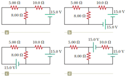
The circuit in Figure P27.34a consists of three resistors and one battery with no internal resistance. (a) Find the current in the 5.00-Ω resistor. (b) Find the power delivered to the 5.00-Ω resistor. (c) In each of the circuits in Figures P27.34b, P27.34c, and P27.34d, an additional 15.0-V battery has been inserted into the circuit. Which diagram or diagrams represent a circuit that requires the use of Kirchhoff’s rules to find the currents? Explain why. (d) In which of these three new circuits is the smallest amount of power delivered to the 10.0-Ω resistor? (You need not calculate the power in each circuit if you explain your answer.)
Figure P27.34
Expert Solution & Answer

Trending nowThis is a popular solution!

Students have asked these similar questions
Four resistors are combined in a circuit along with a battery and an ammeter. The values of the resistors are R1 = 5 Ω, R2 = 5 Ω, R3 = 10 Ω, and R4 = 20 Ω. If the current through the ammeter is 2.6 A and the voltage of the battery is 50 V, what is the configuration of the resistors?
A circuit contains four resistors. Resistor ?1R1 has a resistance of 55.0 Ω , resistor R2 has a resistance of 111 Ω , resistor R3 has a resistance of 71.0 Ω , and resistor R4 has a resistance of 153 Ω .
If the battery has a voltage of V=45.0 V, how much power is dissipated in each resistor?
A circuit contains four resistors. Resistor R1 has a
R.
resistance of 49.0 Q, resistor Rz has a resistance of
1132, resistor R; has a resistance of 87.0 2, and
resistor R4 has a resistance of 167 2.
If the battery has a voltage of V = 45.0 V, how much
power is dissipated in each resistor?
P =
P =
P =
W
P =
Chapter 27 Solutions
Physics:f/sci.+engrs.,ap Ed.
Ch. 27.1 - To maximize the percentage of the power from the...Ch. 27.2 - With the switch in the circuit of Figure 27.4a...Ch. 27.2 - With the switch in the circuit of Figure 27.6a...Ch. 27.2 - Prob. 27.4QQCh. 27.4 - Consider the circuit in Figure 27.17 and assume...Ch. 27 - Two 1.50-V batterieswith their positive terminals...Ch. 27 - As in Example 27.2, consider a power supply with...Ch. 27 - Figure P27.3 shows the interior of a three-way...Ch. 27 - Prob. 4PCh. 27 - Consider the two circuits shown in Figure P27.5 in...
Ch. 27 - Consider strings of incandescent lights that are...Ch. 27 - You are working at an electronics fabrication...Ch. 27 - In your new job at an engineering company, your...Ch. 27 - A battery with = 6.00 V and no internal...Ch. 27 - A battery with emf and no internal resistance...Ch. 27 - Todays class on current and resistance is about to...Ch. 27 - Why is the following situation impossible? A...Ch. 27 - Calculate the power delivered to each resistor in...Ch. 27 - For the purpose of measuring the electric...Ch. 27 - Four resistors are connected to a battery as shown...Ch. 27 - You have a faculty position at a community college...Ch. 27 - The circuit shown in Figure P27.17 is connected...Ch. 27 - The following equations describe an electric...Ch. 27 - Taking R = 1.00 k and = 250 V in Figure P27.19,...Ch. 27 - In the circuit of Figure P27.20, the current I1 =...Ch. 27 - (a) Can the circuit shown in Figure P27.21 be...Ch. 27 - For the circuit shown in Figure P27.22, we wish to...Ch. 27 - An uncharged capacitor and a resistor are...Ch. 27 - Show that the time constant in Equation 27.20 has...Ch. 27 - In the circuit of Figure P27.25, the switch S has...Ch. 27 - In the circuit of Figure P27.25, the switch S has...Ch. 27 - A 10.0-F capacitor is charged by a 10.0-V battery...Ch. 27 - Show that the integral 0e2t/RCdtin Example 27.11...Ch. 27 - You and your roommates are studying hard for your...Ch. 27 - Prob. 30PCh. 27 - Turn on your desk lamp. Pick up the cord, with...Ch. 27 - Four resistors are connected in parallel across a...Ch. 27 - Find the equivalent resistance between points a...Ch. 27 - The circuit in Figure P27.34a consists of three...Ch. 27 - The circuit in Figure P27.35 has been connected...Ch. 27 - The resistance between terminals a and b in Figure...Ch. 27 - (a) Calculate the potential difference between...Ch. 27 - Why is the following situation impossible? A...Ch. 27 - When two unknown resistors are connected in series...Ch. 27 - When two unknown resistors are connected in series...Ch. 27 - The circuit in Figure P27.41 contains two...Ch. 27 - Two resistors R1 and R2 are in parallel with each...Ch. 27 - A power supply has an open-circuit voltage of 40.0...Ch. 27 - A battery is used to charge a capacitor through a...Ch. 27 - An ideal voltmeter connected across a certain...Ch. 27 - (a) Determine the equilibrium charge on the...Ch. 27 - In Figure P27.47, suppose the switch has been...Ch. 27 - Figure P27.48 shows a circuit model for the...Ch. 27 - The student engineer of a campus radio station...Ch. 27 - A voltage V is applied to a series configuration...Ch. 27 - The switch in Figure P27.51a closes when Vc23Vand...
Knowledge Booster


Learn more about
Need a deep-dive on the concept behind this application? Look no further. Learn more about this topic, physics and related others by exploring similar questions and additional content below.Similar questions
- What is the equivalent resistance between points a and b of the six resistors shown in Figure P29.70? FIGURE P29.70arrow_forwardCalculate the power delivered to each resistor in the circuit shown in Figure P21.43. Figure P21.43arrow_forwardIn the circuit of Figure P21.51, determine (a) the current in each resistor and (b) the potential difference across the 200- resistor. Figure P21.51arrow_forward
- (a) Can the circuit shown in Figure P18.29 be reduced to a single resistor connected to the batteries? Explain. (b) Find the magnitude of the current and its direction in each resistor. Figure P18.29arrow_forwardConsider the circuit shown in Figure P21.39. Find (a) the current in the 20.0- resistor and (b) the potential difference between points a and b. Figure P21.39arrow_forwardFigure P29.46 shows a circuit with a 12.0-V battery connected to four resistors. How much power is delivered to each resistor?arrow_forward
- The circuit shown in Figure P21.47 is connected for 2.00 min. (a) Determine the current in each branch of the circuit. (b) Find the energy delivered by each battery. (c) Find the energy delivered to each resistor. (d) Identify the type of energy storage transformation that occurs in the operation of the circuit. (e) Find the total amount of energy transformed into internal energy in the resistors. Figure P21.47 Problems 47 and 48.arrow_forwardConsider the circuit shown in Figure P28.21 on page 860. (a) Find the voltage across the 3.00-0 resistor, (b) Find the current in the 3.00-12 resistor.arrow_forwardFor the circuit shown in Figure P28.55. the ideal voltmeter reads 6.00 V and the ideal ammeter reads 3.00-k. Find (a) the value of K, (b) the emf of the battery, and (c) the voltage across the 3.00-kft resistor.arrow_forward
- If the terminals of a battery with zero internal resistance are connected across two identical resistors in series, the total power delivered by the battery is 8.00 W. If the same battery is connected across the same resistors in parallel, what is the total power delivered by the battery? (a) 16.0 W (b) 32.0 W (c) 2.00 W (d) 4.00 W (e) none of those answersarrow_forwardAn initially uncharged 4.71 x 10- F capacitor and a 8990 2 resistor are connected in series to a 1.50 V battery that has negligible internal resistance. What is the initial current Io in the circuit? Io = Calculate the circuit's time constant r.arrow_forward(a) Find the equivalent resistance of the circuit in Figure P18.8. (R1 = 3.00 N, R2 = 13.0 N) (b) If the total power supplied to the circuit is 1.00 W, find the emf of the battery. R2 4.00 N 5.00 2 R R, Figure P18.8arrow_forward
arrow_back_ios
SEE MORE QUESTIONS
arrow_forward_ios
Recommended textbooks for you
 Principles of Physics: A Calculus-Based TextPhysicsISBN:9781133104261Author:Raymond A. Serway, John W. JewettPublisher:Cengage Learning
 Physics for Scientists and Engineers with Modern ...PhysicsISBN:9781337553292Author:Raymond A. Serway, John W. JewettPublisher:Cengage Learning
 Physics for Scientists and Engineers: Foundations...PhysicsISBN:9781133939146Author:Katz, Debora M.Publisher:Cengage Learning
 College PhysicsPhysicsISBN:9781305952300Author:Raymond A. Serway, Chris VuillePublisher:Cengage Learning
 College PhysicsPhysicsISBN:9781285737027Author:Raymond A. Serway, Chris VuillePublisher:Cengage Learning
 Physics for Scientists and Engineers, Technology ...PhysicsISBN:9781305116399Author:Raymond A. Serway, John W. JewettPublisher:Cengage Learning
Principles of Physics: A Calculus-Based Text
Physics
ISBN:9781133104261
Author:Raymond A. Serway, John W. Jewett
Publisher:Cengage Learning
Physics for Scientists and Engineers with Modern ...
Physics
ISBN:9781337553292
Author:Raymond A. Serway, John W. Jewett
Publisher:Cengage Learning
Physics for Scientists and Engineers: Foundations...
Physics
ISBN:9781133939146
Author:Katz, Debora M.
Publisher:Cengage Learning
College Physics
Physics
ISBN:9781305952300
Author:Raymond A. Serway, Chris Vuille
Publisher:Cengage Learning
College Physics
Physics
ISBN:9781285737027
Author:Raymond A. Serway, Chris Vuille
Publisher:Cengage Learning
Physics for Scientists and Engineers, Technology ...
Physics
ISBN:9781305116399
Author:Raymond A. Serway, John W. Jewett
Publisher:Cengage Learning
How To Solve Any Resistors In Series and Parallel Combination Circuit Problems in Physics; Author: The Organic Chemistry Tutor;https://www.youtube.com/watch?v=eFlJy0cPbsY;License: Standard YouTube License, CC-BY