
Bundle: Physics for Scientists and Engineers with Modern Physics, Loose-leaf Version, 10th + WebAssign Printed Access Card for Serway/Jewett's Physics for Scientists and Engineers, 10th, Multi-Term
10th Edition
ISBN: 9781337888592
Author: Raymond A. Serway, John W. Jewett
Publisher: Cengage Learning
expand_more
expand_more
format_list_bulleted
Videos
Textbook Question
Chapter 27, Problem 36AP
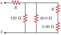
The resistance between terminals a and b in Figure P27.36 is 75.0 Ω. If the resistors labeled R have the same value, determine R.
Figure P27.36
Expert Solution & Answer

Trending nowThis is a popular solution!

Students have asked these similar questions
Two resistors, R1 = 50 Ω and R2 = 17 Ω are connected in series to a battery providing voltage ΔVbat = 3.1 V. What is the potential difference measured across the resistor R2?
Two resistors, R1 = 21 Ω and R2 = 35 Ω are connected in parallel across a battery providing voltage ΔVbat = 5.7 V. What is the current through resistor R1?
Can you solve the question below?
Chapter 27 Solutions
Bundle: Physics for Scientists and Engineers with Modern Physics, Loose-leaf Version, 10th + WebAssign Printed Access Card for Serway/Jewett's Physics for Scientists and Engineers, 10th, Multi-Term
Ch. 27.1 - To maximize the percentage of the power from the...Ch. 27.2 - With the switch in the circuit of Figure 27.4a...Ch. 27.2 - With the switch in the circuit of Figure 27.6a...Ch. 27.2 - Prob. 27.4QQCh. 27.4 - Consider the circuit in Figure 27.17 and assume...Ch. 27 - Two 1.50-V batterieswith their positive terminals...Ch. 27 - As in Example 27.2, consider a power supply with...Ch. 27 - Figure P27.3 shows the interior of a three-way...Ch. 27 - Prob. 4PCh. 27 - Consider the two circuits shown in Figure P27.5 in...
Ch. 27 - Consider strings of incandescent lights that are...Ch. 27 - You are working at an electronics fabrication...Ch. 27 - In your new job at an engineering company, your...Ch. 27 - A battery with = 6.00 V and no internal...Ch. 27 - A battery with emf and no internal resistance...Ch. 27 - Todays class on current and resistance is about to...Ch. 27 - Why is the following situation impossible? A...Ch. 27 - Calculate the power delivered to each resistor in...Ch. 27 - For the purpose of measuring the electric...Ch. 27 - Four resistors are connected to a battery as shown...Ch. 27 - You have a faculty position at a community college...Ch. 27 - The circuit shown in Figure P27.17 is connected...Ch. 27 - The following equations describe an electric...Ch. 27 - Taking R = 1.00 k and = 250 V in Figure P27.19,...Ch. 27 - In the circuit of Figure P27.20, the current I1 =...Ch. 27 - (a) Can the circuit shown in Figure P27.21 be...Ch. 27 - For the circuit shown in Figure P27.22, we wish to...Ch. 27 - An uncharged capacitor and a resistor are...Ch. 27 - Show that the time constant in Equation 27.20 has...Ch. 27 - In the circuit of Figure P27.25, the switch S has...Ch. 27 - In the circuit of Figure P27.25, the switch S has...Ch. 27 - A 10.0-F capacitor is charged by a 10.0-V battery...Ch. 27 - Show that the integral 0e2t/RCdtin Example 27.11...Ch. 27 - You and your roommates are studying hard for your...Ch. 27 - Prob. 30PCh. 27 - Turn on your desk lamp. Pick up the cord, with...Ch. 27 - Four resistors are connected in parallel across a...Ch. 27 - Find the equivalent resistance between points a...Ch. 27 - The circuit in Figure P27.34a consists of three...Ch. 27 - The circuit in Figure P27.35 has been connected...Ch. 27 - The resistance between terminals a and b in Figure...Ch. 27 - (a) Calculate the potential difference between...Ch. 27 - Why is the following situation impossible? A...Ch. 27 - When two unknown resistors are connected in series...Ch. 27 - When two unknown resistors are connected in series...Ch. 27 - The circuit in Figure P27.41 contains two...Ch. 27 - Two resistors R1 and R2 are in parallel with each...Ch. 27 - A power supply has an open-circuit voltage of 40.0...Ch. 27 - A battery is used to charge a capacitor through a...Ch. 27 - An ideal voltmeter connected across a certain...Ch. 27 - (a) Determine the equilibrium charge on the...Ch. 27 - In Figure P27.47, suppose the switch has been...Ch. 27 - Figure P27.48 shows a circuit model for the...Ch. 27 - The student engineer of a campus radio station...Ch. 27 - A voltage V is applied to a series configuration...Ch. 27 - The switch in Figure P27.51a closes when Vc23Vand...
Knowledge Booster


Learn more about
Need a deep-dive on the concept behind this application? Look no further. Learn more about this topic, physics and related others by exploring similar questions and additional content below.Similar questions
- Three resistors, R1 = 17.3, R2 = 13.2, R3 = 78, are connected in series across a 16.6 V battery. What is the voltage drop (in Volts) across R1?arrow_forwardThe emf source, E. of the circuit shown in the figure has negligible internal resistance. The resistors have resistances R= 6.62 and R,=4.92. The capacitor has a capacitance C 13.4 uF When the capacitor is fully charged, the magnitude of the charge on its plates is Q 17.1 uC. What is E in units of Volts? R2 O 4.4 O 2.2 R1 O 3.1 O 0.22 O 1.1arrow_forwardThree resistors are connected as shown below. R1 = 3.0 Ω, R2 = 6.0 Ω, and R3 = 8.0 Ω. The voltage across the battery is 60 V. What is the current through R1, in Amperes?arrow_forward
- Two batteries with emf ℰ = 10 V and internal resistance r = 4 Ω and a resistor with R0 = 45 Ω are connected in series as shown in the figure. a. Express the total resistance, R, in terms of r and R0. b. Express the current, I, in terms of the emf, ℰ, and the total resistance, R. c. Express the voltage, ΔV, across the resister in terms of I and R0. d. Calculate the value of ΔV in volts.arrow_forwardThree resistors, R1 = 2.55 Ω, R2 = 4.77 Ω, and R3 = 6.55 Ω are connected by ideal metal wires, as shown in the figure. If the voltage dropping through R1 is 3.49 V, what is the voltage difference between points a and b (in V).arrow_forwardIn the circuit pictured, the resistors have values of R1 = 170 Q, R, = 62 Q, and R3 = 130 Q, and the battery has an emf ɛ = 274 V. R R2 R3 A. How much current ibatt, in amperes, goes through the battery? B. What is the current i2, in amperes, through resistor R2?arrow_forward
- The circuit in Figure P28.43 has been connected for a long time. (a) What is the potential difference acros:s the capacitor? (b) If the battery is disconnected from the circuit, over what time interval does the capacitor discharge to one-tenth its initial voltage? 1.00 Ω 8.00 Ω 1.00 μF 0.0 V 4.00 Ω 2.00 Ωarrow_forwardA heart pacemaker fires 67 times a minute. Each time it fires, a 35.0 nF capacitor is charged by a battery in series with a resistor to 0.682 of its full voltage. What is the resistance?arrow_forwardA battery has emf 30.0 V and internal resistance r. A 9.00 Ω resistor is connected to the terminals of the battery, and the voltage drop across the resistor is 27.0 V. What is the internal resistance of the battery?arrow_forward
- R1 = 35 Ω, R2 = 20 Ω, and R3 = 15 Ω. The battery supplies an emf of ε = 220V. What is the equivalent resistance, RS ? What is the current through each resistor? What is the voltage drop across each resistor?arrow_forwardFigure P18.19 shows a circuit diagram. (R1 = 1490 2, R2 = 420 , AV = 28.0 V) 1 000 N R, 30.0 V AV 2 000 ? 20.0 V Figure P18.19 (a) Determine the current. mA (b) Determine the potential of wire A relative to ground. V (c) Determine the voltage drop across the 1490 2 resistor. Varrow_forwardWhat is the current (in A) passing through resistor 3 in the circuit if V = 12 V, R1 = 18 Q, R2 = 6 Q, and R3 = 3 0? Give your answer as only the numerical value in the SI units specified. e is interpreted as x10^ for use with large or small values; 1.01e2 is interpreted as 1.01 x 10². R1 R2 R3arrow_forward
arrow_back_ios
SEE MORE QUESTIONS
arrow_forward_ios
Recommended textbooks for you
 Physics for Scientists and EngineersPhysicsISBN:9781337553278Author:Raymond A. Serway, John W. JewettPublisher:Cengage Learning
 Physics for Scientists and Engineers with Modern ...PhysicsISBN:9781337553292Author:Raymond A. Serway, John W. JewettPublisher:Cengage Learning
Physics for Scientists and Engineers
Physics
ISBN:9781337553278
Author:Raymond A. Serway, John W. Jewett
Publisher:Cengage Learning
Physics for Scientists and Engineers with Modern ...
Physics
ISBN:9781337553292
Author:Raymond A. Serway, John W. Jewett
Publisher:Cengage Learning
DC Series circuits explained - The basics working principle; Author: The Engineering Mindset;https://www.youtube.com/watch?v=VV6tZ3Aqfuc;License: Standard YouTube License, CC-BY