
FUND OF PHYS W/ WILEYPLUS
11th Edition
ISBN: 9781119492023
Author: Halliday
Publisher: WILEY
expand_more
expand_more
format_list_bulleted
Videos
Textbook Question
Chapter 27, Problem 80P
In Fig. 27-73, R1 = 5.00 Ω, R2 = 10.0 Ω, R3 = 15.0 Ω, C1 = 5.00 μF, C2=10.0 μF, and the ideal battery has emf ℰ = 20.0 V. Assuming that the circuit is in the steady state, what is the total energy stored in the two capacitors?
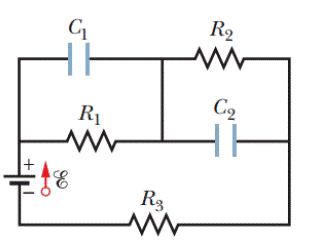
Figure 27-73 Problem 80.
Expert Solution & Answer

Trending nowThis is a popular solution!

Students have asked these similar questions
Three (3) 2.0 F capacitors are connected in three (3) configurations, as shown in the given image.
X
Y
The equivalent capacitances for the arrangements are Cx, Cy, and Cz, respectively. Which of these comparisons of Cx, Cy, and
Cz is TRUE?
Select the correct response:
Cx > Cz > Cy
Cx > Cy > Cz
Cz > Cy > Cx
Cy > Cz > Cx
In the figure R₁ = 5.03 Q2, R₂ = 10.11 02, R3 = 15.040,
C₁ = 5.19 µF, C₂ = 10.25 µF, and the ideal battery has
emf & = 22.3 V. Assuming that the circuit is in the
steady state, what is the total energy stored in the
two capacitors?
Number i
G₁
HH
R₁
www
18
R$
M
R₂
M
C₂
Units
µJ
Problem 25: Two capacitors are connected in a circuit in series as shown in the figure. The
capacitances are C1= 35 µF, and C2 = 9.5 µF.
C2
©theexpertta.com
» Part (a) Express the total capacitance C in terms of the two capacitances C1 and C2.
C = L
a
AV
7
8
9
HOME
C1
C2
4
5
6
d.
h
1
2
3
i
k
-
END
P
VO BACKSPACE
CLEAR
m
DEL
Submit
Hint
Feedback
I give up!
Hints: 0% deduction per hint. Hints remaining: 1
Feedback: 1% deduction per feedback.
Part (b) Calculate the numerical value of the total capacitance C in µF?
Part (c) If the battery carries a voltage of AV, express the total charge Q stored in the circuit in terms of capacitance C and voltage AV.
Part (d) Calculate the numerical value of Q in C given AV = 15 V.
Chapter 27 Solutions
FUND OF PHYS W/ WILEYPLUS
Ch. 27 - a In Fig. 27-18a, with R1R2, is the potential...Ch. 27 - a In Fig. 27-18a, are resistors R1 and R3 in...Ch. 27 - You are to connect resistors R1 and R2, with R1R2,...Ch. 27 - In Fig. 27-19, a circuit consists of a battery and...Ch. 27 - For each circuit in Fig 27-20, are the resistors...Ch. 27 - Res-monster maze. In Fig. 27-21, all the resistors...Ch. 27 - A resistor R1 is wired to a battery, then resistor...Ch. 27 - What is the equivalent resistance of three...Ch. 27 - Two resistors are wired to a battery. a In which...Ch. 27 - Cap-monster maze. In Fig. 27-22, all the...
Ch. 27 - Initially, a single resistor, R1 is wired to a...Ch. 27 - After the switch in Fig. 27-15 is closed on point...Ch. 27 - Figure 27-24 shows three sections of circuit that...Ch. 27 - SSM WWW In Fig. 27-25, the ideal batteries have...Ch. 27 - In Fig. 27-26, the ideal batteries have emfs 1 =...Ch. 27 - ILW A car battery with a 12 V emf and an internal...Ch. 27 - GO Figure 27-27 shows a circuit of four resistors...Ch. 27 - A 5.0 A current is set up in a circuit for 6.0 min...Ch. 27 - A standard flashlight battery can deliver about...Ch. 27 - A wire of resistance 5.0 is connected to a...Ch. 27 - A certain car battery with a 12.0 V emf has an...Ch. 27 - a In electron-volts, how much work does an ideal...Ch. 27 - a In Fig. 27-28, what value must R have if the...Ch. 27 - SSM In Fig. 27-29, circuit section AB absorbs...Ch. 27 - Figure 27-30 shows a resistor of resistance R =...Ch. 27 - A 10-km-long underground cable extends east to...Ch. 27 - GO In Fig. 27-32a, both batteries have emf = 1.20...Ch. 27 - ILW The current in a single-loop circuit with one...Ch. 27 - A solar cell generates a potential difference of...Ch. 27 - SSM In Fig. 27-33, battery 1 has emf 1 = 12.0 V...Ch. 27 - In Fig. 27-9, what is the potential difference Vd ...Ch. 27 - A total resistance of 3.00 is to be produced by...Ch. 27 - When resistors 1 and 2 are connected in series,...Ch. 27 - Prob. 21PCh. 27 - Figure 27-34 shows five 5.00 resistors. Find the...Ch. 27 - In Fig. 27-35, R1 = 100 , R2 = 50 , and the ideal...Ch. 27 - In Fig. 27-36, R1 = R2 = 4.00 and R3 = 2.50 ....Ch. 27 - SSM Nine copper wires of length l and diameter d...Ch. 27 - Figure 27-37 shows a battery connected across a...Ch. 27 - Side flash. Figure 27-38 indicates one reason no...Ch. 27 - The ideal battery in Fig. 27-39a has emf = 6.0 V....Ch. 27 - In Fig. 27-40, R1 = 6.00 , R2 = 18.0 , and the...Ch. 27 - GO In Fig. 27-41, the ideal batteries have emfs 1...Ch. 27 - SSMGO In Fig. 27-42, the ideal batteries have emfs...Ch. 27 - Both batteries in Fig. 27-43a are ideal. Emf 1 of...Ch. 27 - GO In Fig. 27-44. the current in resistance 6 is...Ch. 27 - The resistances in Figs. 27-45a and b are all 6.0...Ch. 27 - GO In Fig. 27-46, = 12.0 V, R1, = 2000 , R2 =...Ch. 27 - GO In Fig. 27-47, 1 = 6.00 V, 2 = 12.0 V, R1, =...Ch. 27 - In Fig. 27-48, the resistances are R1 = 2.00 , R2...Ch. 27 - Figure 27-49 shows a section of a circuit. The...Ch. 27 - GO In Fig. 27-50, two batteries with an emf =...Ch. 27 - GO Two identical batteries of emf = 12.0 V and...Ch. 27 - In Fig. 27-41, 1 = 3.00 V, 2 = 1.00 V, R1 = 4.00 ,...Ch. 27 - In Fig. 27-52, an array of n parallel resistors is...Ch. 27 - You are given a number of 10 resistors, each...Ch. 27 - GO In Fig. 27-53, R1 = 100 , R2 = R3 = 50.0 , R4 =...Ch. 27 - ILW In Fig. 27-54, the resistances are R1 = 1.0 ...Ch. 27 - In Fig. 27-55a, resistor 3 is a variable resistor...Ch. 27 - SSM A copper wire of radius a = 0.250 mm has an...Ch. 27 - GO In Fig. 27-53, the resistors have the values R1...Ch. 27 - ILW a In Fig. 27-56, what current does the ammeter...Ch. 27 - In Fig. 27-57, R1 = 2.00R, the ammeter resistance...Ch. 27 - In Fig. 27-58, a voltmeter of resistance Rv= 300 ...Ch. 27 - A simple ohmmeter is made by connecting a 1.50V...Ch. 27 - Prob. 53PCh. 27 - When the lights of a car are switched on, an...Ch. 27 - In Fig. 27-61, Rsis to be adjusted in value by...Ch. 27 - In Fig. 27-62. a voltmeter of resistance Rv = 300 ...Ch. 27 - Switch S in Fig. 27-63 is closed at time t = 0, to...Ch. 27 - In an RC series circuit, emf = 12.0 V, resistance...Ch. 27 - SSM What multiple of the time constant gives the...Ch. 27 - A capacitor with initial charge q0 is discharge...Ch. 27 - ILW A 15.0 k resistor and a capacitor are...Ch. 27 - Figure 27-64 shows the circuit of a flashing lamp,...Ch. 27 - SSM WWWIn the circuit of Fig. 27-65, = 1.2 kV, C=...Ch. 27 - A capacitor with an initial potential difference...Ch. 27 - GO In Fig. 27-66. R1 = 10.0 k, R2 = 15.0 k, C=...Ch. 27 - Figure 27-67 display two circuits with a charged...Ch. 27 - The potential difference between the plates of a...Ch. 27 - A 1.0 F capacitor with an initial stored energy of...Ch. 27 - GO A 3.00 M resistor and a 1.00 F capacitor are...Ch. 27 - GO Each of the six real batteries in Fig. 27-68...Ch. 27 - In Fig. 27-69, R1 = 20.0 , R2 = 10.0 , and the...Ch. 27 - In Fig.27-70, the ideal battery has emf = 30.0 V,...Ch. 27 - SSM Wires A and B, having equal lengths of 40.0 m...Ch. 27 - What are the a size and b direction up or down of...Ch. 27 - Suppose that, while you are sitting in a chair,...Ch. 27 - GO In Fig. 27-72, the ideal batteries have emfs 1...Ch. 27 - SSM A temperature-stable resistor is made by...Ch. 27 - In Fig. 27-14, assume that = 5.0 V, r = 2.0 , R1...Ch. 27 - Prob. 79PCh. 27 - In Fig. 27-73, R1 = 5.00 , R2 = 10.0 , R3 = 15.0 ,...Ch. 27 - In Fig. 27-5a, find the potential difference...Ch. 27 - In Fig. 27-8a, calculate the potential difference...Ch. 27 - SSM A controller on an electronic arcade game...Ch. 27 - An automobile gasoline gauge is shown...Ch. 27 - SSM The starting motor of a car is turning too...Ch. 27 - Two resistors R1 and R2 may be connected either in...Ch. 27 - The circuit of Fig. 27-25 shows a capacitor, two...Ch. 27 - In Fig. 27-41, R1 = 10.0 , R2 = 20.0 , and the...Ch. 27 - In Fig. 27-76, R= 10 . what is the equivalent...Ch. 27 - a In Fig. 27-4a, show that the rate at which...Ch. 27 - In Fig. 27-77, the ideal batteries have emfs 1 =...Ch. 27 - Figure 27-28 shows a portion of a circuit through...Ch. 27 - Thermal energy is to be generated in a 0.10 ...Ch. 27 - Figure 27-29 shows three 20.0 resistors. Find the...Ch. 27 - A 120 V power line is protected by a 15 A fuse....Ch. 27 - Figure 27-63 shows an ideal battery of emf = 12...Ch. 27 - SSM A group of N identical batteries of emf and...Ch. 27 - Prob. 98PCh. 27 - SSM In Fig. 27-66, the ideal battery has emf = 30...Ch. 27 - In Fig. 27-81, the ideal batteries have emfs 1 =...Ch. 27 - In Fig. 27-82, an ideal battery of emf = 12.0 V...Ch. 27 - The following table gives the electric potential...Ch. 27 - In Fig. 27-83, 1 = 6.00 V, 2 = 12.0 V, R1= 200 ...Ch. 27 - A three-way 120 V lamp bulb that contains two...Ch. 27 - In Fig. 27-84, R1 = R2 = 2.0 , R3 = 4.0 , R4 = 3.0...
Additional Science Textbook Solutions
Find more solutions based on key concepts
Can the Compton effect occur with visible light? If so, will it be detectable?
University Physics Volume 3
The ratio of angular speeds for a spinning skater with outstretched arms and with arms held tightly against her...
Physics: Principles with Applications
Name the fundamental force involved in (a) binding of a proton and a neutron to make a deuterium nucleus; (b) d...
Essential University Physics: Volume 2 (3rd Edition)
56. Global Positioning System. Learn more about the global positioning system and its uses. Write a short repo...
The Cosmic Perspective (8th Edition)
Airbags cushioned the Mars rover Spirits landing, and the rover bounced some 15 m vertically after its first im...
Essential University Physics: Volume 1 (3rd Edition)
18. A 1.0 kg block is attached to a spring with spring constant 16 N/m. While the block is sitting at rest, a s...
Physics for Scientists and Engineers: A Strategic Approach, Vol. 1 (Chs 1-21) (4th Edition)
Knowledge Booster


Learn more about
Need a deep-dive on the concept behind this application? Look no further. Learn more about this topic, physics and related others by exploring similar questions and additional content below.Similar questions
- A capacitor with initial charge Q0 is connected across a resistor R at time t = 0. The separation between the plates of the capacitor changes as d = d0/(1 + t) for 0 t 1 s. Find an expression for the voltage drop across the capacitor as a function of time.arrow_forwardAccording to UE=12C(V)2 (Eq. 27.3), a greater capacitance means more energy is stored by the capacitor, but according to UE = Q2/2C (Eq. 27.2), a greater capacitance means less energy is stored. How can both of these equations be correct?arrow_forwardConsider the circuit shown in Figure P20.52, where C1 = 6.00 F, C2 = 3.00 F, and V = 20.0 V. Capacitor C1 is first charged by closing switch S1. Switch S1 is then opened, and the charged capacitor is connected to the uncharged capacitor by closing S2. Calculate (a) the initial charge acquired by C1 and (b) the final charge on each capacitor. Figure P20.52arrow_forward
- Assume a length of axon membrane of about 0.10 m is excited by an action potential (length excited = nerve speed pulse duration = 50.0 m/s 2.0 103 s = 0.10 m). In the resting state, the outer surface of the axon wall is charged positively with K+ ions and the inner wall has an equal and opposite charge of negative organic ions, as shown in Figure P18.43. Model the axon as a parallel-plate capacitor and take C = 0A/d and Q = C V to investigate the charge as follows. Use typical values for a cylindrical axon of cell wall thickness d = 1.0 108 m, axon radius r = 1.0 101 m, and cell-wall dielectric constant = 3.0. (a) Calculate the positive charge on the outside of a 0.10-m piece of axon when it is not conducting an electric pulse. How many K+ ions are on the outside of the axon assuming an initial potential difference of 7.0 102 V? Is this a large charge per unit area? Hint: Calculate the charge per unit area in terms of electronic charge e per squared (2). An atom has a cross section of about 1 2 (1 = 1010 m). (b) How much positive charge must flow through the cell membrane to reach the excited state of + 3.0 102 V from the resting state of 7.0 102 V? How many sodium ions (Na+) is this? (c) If it takes 2.0 ms for the Na+ ions to enter the axon, what is the average current in the axon wall in this process? (d) How much energy does it take to raise the potential of the inner axon wall to + 3.0 102 V, starting from the resting potential of 7.0 102 V? Figure P18.43 Problem 43 and 44.arrow_forwardAccording to its design specification, the timer circuit delaying the closing of an elevator door is to have a capacitance of 32.0 F between two points A and B. When one circuit is being constructed, the inexpensive but durable capacitor installed between these two points is found to have capacitance 34.8 F. To meet the specification, one additional capacitor can be placed between the two points. (a) Should it be in series or in parallel with the 34.8-F capacitor? (b) What should be its capacitance? (c) What If? The next circuit comes down the assembly line with capacitance 29.8 F between A and B. To meet the specification, what additional capacitor should be installed in series or in parallel in that circuit?arrow_forwardThe temperature near the center of the Sun is thought to be 15 million degrees Celsius ( 1.5107oC ) (or kelvin). Through what voltage must a singly charged ion be accelerated to have the same energy as the average kinetic energy of ions at this temperature?arrow_forward
- 80 In Fig. 27-73, R1 = 5.00 0, R2 = 10.0 0, R3= 15.0 n, C= 5.00 µF, |C = 10.0 µF, and the ideal battery R. %3D has emf & = 20.0 V.Assuming that the circuit is in the steady state, what is the total energy stored in the two R1 C2 capacitors?arrow_forwardTwo capacitors with capacitance values C1 = 2000 ± 10 pF and C2 = 3000 ± 15 pF are connected in series. The voltage applied across this combination is ? = 5.00 ± 0.02 V. The percentage error in the calculation of the energy stored in this combination of capacitors isarrow_forwardThree capacitors C, = 11.0 µF, C2 = 16.0 µF, and C3 = 28.6 µF are connected in series. To avoid breakdown of the capacitors, the maximum potential difference to which any of them can be individually charged is 125 V. Determine the maximum energy stored in the series combination.arrow_forward
- Q (C) capacitor P kapasitor P 0.63 Q. 0.37 Q. 2 uF 3 µF 37 80 5 uF (a) (b) FIGURE 2 RAJAH 2 The graph in FIGURE 2(a) shows how the charge, Q on a capacitor P changes with time, I when it is charged through a 20 Q resistor. Determine the capacitance of capacitor P. (a) Graf dalam RAJAH 2(a) menunjukkan bagaimana cas, Q pada satu kapasitor P berubah dengan masa, t apabila ia dicas melalui satu perintang 20 2. Tentukan kapasitans bagi kapasitor P. (b) Capacitor P is then arranged as shown in FIGURE 2(b). Determine the effective capacitance. Kapasitor P kemudian disusun seperti RAJAH 2(b). Tentukan kapasitans berkesan. 2.arrow_forwardSY:YO 10 J غير مجاب عليه بعد 10.00 dajal علم هذا السؤال Find the total energy stored (in units of mJ) in the group of capacitors shown below given that the potential ?difference Vab is equal to 58.4 V 50 µF HH 10 μF HH 20 μΕarrow_forwardHow should 4 capacitors, C1 = 2 µF, C2 = 4 µF, C3 = 6 µF and C4 = 8 µF be connected to have a total effective capacitance of 4.20 µF?arrow_forward
arrow_back_ios
SEE MORE QUESTIONS
arrow_forward_ios
Recommended textbooks for you
 Principles of Physics: A Calculus-Based TextPhysicsISBN:9781133104261Author:Raymond A. Serway, John W. JewettPublisher:Cengage Learning
 Physics for Scientists and Engineers: Foundations...PhysicsISBN:9781133939146Author:Katz, Debora M.Publisher:Cengage Learning
 College PhysicsPhysicsISBN:9781305952300Author:Raymond A. Serway, Chris VuillePublisher:Cengage Learning
Principles of Physics: A Calculus-Based Text
Physics
ISBN:9781133104261
Author:Raymond A. Serway, John W. Jewett
Publisher:Cengage Learning
Physics for Scientists and Engineers: Foundations...
Physics
ISBN:9781133939146
Author:Katz, Debora M.
Publisher:Cengage Learning
College Physics
Physics
ISBN:9781305952300
Author:Raymond A. Serway, Chris Vuille
Publisher:Cengage Learning
DC Series circuits explained - The basics working principle; Author: The Engineering Mindset;https://www.youtube.com/watch?v=VV6tZ3Aqfuc;License: Standard YouTube License, CC-BY