
PHYSICS FOR SCI.AND ENGR W/WEBASSIGN
10th Edition
ISBN: 9781337888462
Author: SERWAY
Publisher: CENGAGE L
expand_more
expand_more
format_list_bulleted
Videos
Textbook Question
Chapter 27, Problem 9P
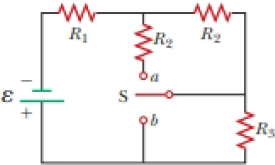
A battery with ε = 6.00 V and no internal resistance supplies current to the circuit shown in Figure P27.9. When the double-throw switch S is open as shown in the figure, the current in the battery is 1.00 mA. When the switch is closed in position a, the current in the battery is 1.20 mA. When the switch is closed in position b, the current in the battery is 2.00 mA. Find the resistances (a) R1, (b) R2, and (c) R3.
Figure P27.9 Problems 9 and 10.
Expert Solution & Answer

Trending nowThis is a popular solution!

Students have asked these similar questions
A battery with Ɛ = 6.00 V
and no internal resistance
supplies current to the
circuit shown in Figure P18.14. When the double-throw switch
S is open as shown in the figure, the current in the battery is
1.00 mA. When the switch is closed in position a, the current
in the battery is 1.20 mA. When the switch is closed in position
b, the current in the battery is 2.00 mA. Find the resistances
(a) R1, (b) R2, and (c) Rg.
R2
R2
R1
ob
ER3
Figure P18.14
Problem in picture below.
A capacitor charging circuit consists of a battery, an uncharged 20 μF capacitor, and a 4.0 kΩ resistor. At t = 0 s, the switch is closed; 0.15 s later, the current is 0.46 mA. What is the battery’s emf?
Chapter 27 Solutions
PHYSICS FOR SCI.AND ENGR W/WEBASSIGN
Ch. 27.1 - To maximize the percentage of the power from the...Ch. 27.2 - With the switch in the circuit of Figure 27.4a...Ch. 27.2 - With the switch in the circuit of Figure 27.6a...Ch. 27.2 - Prob. 27.4QQCh. 27.4 - Consider the circuit in Figure 27.17 and assume...Ch. 27 - Two 1.50-V batterieswith their positive terminals...Ch. 27 - As in Example 27.2, consider a power supply with...Ch. 27 - Figure P27.3 shows the interior of a three-way...Ch. 27 - Prob. 4PCh. 27 - Consider the two circuits shown in Figure P27.5 in...
Ch. 27 - Consider strings of incandescent lights that are...Ch. 27 - You are working at an electronics fabrication...Ch. 27 - In your new job at an engineering company, your...Ch. 27 - A battery with = 6.00 V and no internal...Ch. 27 - A battery with emf and no internal resistance...Ch. 27 - Todays class on current and resistance is about to...Ch. 27 - Why is the following situation impossible? A...Ch. 27 - Calculate the power delivered to each resistor in...Ch. 27 - For the purpose of measuring the electric...Ch. 27 - Four resistors are connected to a battery as shown...Ch. 27 - You have a faculty position at a community college...Ch. 27 - The circuit shown in Figure P27.17 is connected...Ch. 27 - The following equations describe an electric...Ch. 27 - Taking R = 1.00 k and = 250 V in Figure P27.19,...Ch. 27 - In the circuit of Figure P27.20, the current I1 =...Ch. 27 - (a) Can the circuit shown in Figure P27.21 be...Ch. 27 - For the circuit shown in Figure P27.22, we wish to...Ch. 27 - An uncharged capacitor and a resistor are...Ch. 27 - Show that the time constant in Equation 27.20 has...Ch. 27 - In the circuit of Figure P27.25, the switch S has...Ch. 27 - In the circuit of Figure P27.25, the switch S has...Ch. 27 - A 10.0-F capacitor is charged by a 10.0-V battery...Ch. 27 - Show that the integral 0e2t/RCdtin Example 27.11...Ch. 27 - You and your roommates are studying hard for your...Ch. 27 - Prob. 30PCh. 27 - Turn on your desk lamp. Pick up the cord, with...Ch. 27 - Four resistors are connected in parallel across a...Ch. 27 - Find the equivalent resistance between points a...Ch. 27 - The circuit in Figure P27.34a consists of three...Ch. 27 - The circuit in Figure P27.35 has been connected...Ch. 27 - The resistance between terminals a and b in Figure...Ch. 27 - (a) Calculate the potential difference between...Ch. 27 - Why is the following situation impossible? A...Ch. 27 - When two unknown resistors are connected in series...Ch. 27 - When two unknown resistors are connected in series...Ch. 27 - The circuit in Figure P27.41 contains two...Ch. 27 - Two resistors R1 and R2 are in parallel with each...Ch. 27 - A power supply has an open-circuit voltage of 40.0...Ch. 27 - A battery is used to charge a capacitor through a...Ch. 27 - An ideal voltmeter connected across a certain...Ch. 27 - (a) Determine the equilibrium charge on the...Ch. 27 - In Figure P27.47, suppose the switch has been...Ch. 27 - Figure P27.48 shows a circuit model for the...Ch. 27 - The student engineer of a campus radio station...Ch. 27 - A voltage V is applied to a series configuration...Ch. 27 - The switch in Figure P27.51a closes when Vc23Vand...
Knowledge Booster


Learn more about
Need a deep-dive on the concept behind this application? Look no further. Learn more about this topic, physics and related others by exploring similar questions and additional content below.Similar questions
- In the circuit of Figure P27.25, the switch S has been open for a long time. It is then suddenly closed. Determine the time constant (a) before the switch is closed and (b) after the switch is closed. (c) Let the switch be closed at t = 0. Determine the current in the switch as a function of time. Figure P27.25 Problems 25 and 26.arrow_forwardIn the circuit of Figure P21.57, the switch S has been open for a long time. It is then suddenly closed. Take = 10.0 V, R1 = 50.0 k, R2 = 100 k, and C = 10.0 F. Determine the time constant (a) before the switch is closed and (b) after the switch is closed. (c) Let the switch be closed at t = 0. Determine the current in the switch as a function of time.arrow_forwardThe emfs in Figure P29.43 are 1 = 6.00 V and 2 = 12.0 V. The resistances are R1 = 15.0 , R2 = 30.0 , R3 = 45.0 , and R4 = 60.0 . Find the current in each resistor when the switch is a. open and b. closed.arrow_forward
- Consider a series RC circuit as in Figure P28.38 for which R = 1.00 M, C = 5.00 F, and = 30.0 V. Find (a) the time constant of the circuit and (b) the maximum charge on the capacitor after the switch is thrown closed. (c) Find the current in the resistor 10.0 s after the switch is closed.arrow_forwardThe circuit shown in Figure P28.78 is set up in the laboratory to measure an unknown capacitance C in series with a resistance R = 10.0 M powered by a battery whose emf is 6.19 V. The data given in the table are the measured voltages across the capacitor as a function of lime, where t = 0 represents the instant at which the switch is thrown to position b. (a) Construct a graph of In (/v) versus I and perform a linear least-squares fit to the data, (b) From the slope of your graph, obtain a value for the time constant of the circuit and a value for the capacitance. v(V) t(s) In (/v) 6.19 0 5.56 4.87 4.93 11.1 4.34 19.4 3.72 30.8 3.09 46.6 2.47 67.3 1.83 102.2arrow_forwardAt one instant, a current of 6.0 A flows through part of a circuit as shown in Figure P33.12. Determine the instantaneous potential difference between points A and B if the current starts to decrease at a constant rate of 1.0 102 A/s. FIGURE P33.12arrow_forward
- For the circuit shown in Figure P28.55. the ideal voltmeter reads 6.00 V and the ideal ammeter reads 3.00-k. Find (a) the value of K, (b) the emf of the battery, and (c) the voltage across the 3.00-kft resistor.arrow_forwardFigure P29.84 shows a circuit that consists of two identical emf devices. If R1 = R2 = R and the switch is closed, find an expression (in terms of R and ) for the current I that is in the branch from point a to b.arrow_forwardA battery with emf ? and no internal resistance supplies current to the circuit shown in the figure below. When the double-throw switch S is open, the current in the battery is I0. When the switch is closed in position a, the current in the battery is Ia. When the switch is closed in position b, the current in the battery is Ib. Find the resistances (a) R1, (b) R2, and (c) R3.arrow_forward
- The switch in the circuit below has been in position a for a long time. At time t = 0 the switch is thrown to position b. You are given the data: Vb = 36 V, C = 8 μF. Vc is the voltage across the capacitor. If the charge on the capacitor at time t = 0.3 msec after the switch is thrown is 54.1 μC, what is the value of the resistor R? a) 89.71 Ω b) 44.86 Ω c) 22.43 Ω d) Not enough information.arrow_forwardYou connect a battery, resistor, and capacitor as shown in Figure, where s = 36.0 V, C = 5.00 μF, and R = 120 Q2. The switch $ is closed at t=0. (a) When the voltage across the capacitor is 8.00 V, what is the magnitude of the current in the circuit? (b) At what time t after the switch is closed is the voltage across the capacitor 8.00 V? (c) When the voltage across the capacitor is 8.00 V, at what rate is energy being stored in the capacitor? ation i0 ww Switch open q=0arrow_forwardin the circuit below, when the switch S is open, the current through R1is i1(open)= 1.636 A. When the switch is closed,this current changes to i1(closed)= 1.565 A. What are the emf and internal resistance of the battery?arrow_forward
arrow_back_ios
SEE MORE QUESTIONS
arrow_forward_ios
Recommended textbooks for you
 Physics for Scientists and EngineersPhysicsISBN:9781337553278Author:Raymond A. Serway, John W. JewettPublisher:Cengage Learning
 Physics for Scientists and Engineers with Modern ...PhysicsISBN:9781337553292Author:Raymond A. Serway, John W. JewettPublisher:Cengage Learning
 Physics for Scientists and Engineers: Foundations...PhysicsISBN:9781133939146Author:Katz, Debora M.Publisher:Cengage Learning
 Principles of Physics: A Calculus-Based TextPhysicsISBN:9781133104261Author:Raymond A. Serway, John W. JewettPublisher:Cengage Learning
 Physics for Scientists and Engineers, Technology ...PhysicsISBN:9781305116399Author:Raymond A. Serway, John W. JewettPublisher:Cengage Learning
Physics for Scientists and Engineers
Physics
ISBN:9781337553278
Author:Raymond A. Serway, John W. Jewett
Publisher:Cengage Learning
Physics for Scientists and Engineers with Modern ...
Physics
ISBN:9781337553292
Author:Raymond A. Serway, John W. Jewett
Publisher:Cengage Learning
Physics for Scientists and Engineers: Foundations...
Physics
ISBN:9781133939146
Author:Katz, Debora M.
Publisher:Cengage Learning
Principles of Physics: A Calculus-Based Text
Physics
ISBN:9781133104261
Author:Raymond A. Serway, John W. Jewett
Publisher:Cengage Learning
Physics for Scientists and Engineers, Technology ...
Physics
ISBN:9781305116399
Author:Raymond A. Serway, John W. Jewett
Publisher:Cengage Learning
DC Series circuits explained - The basics working principle; Author: The Engineering Mindset;https://www.youtube.com/watch?v=VV6tZ3Aqfuc;License: Standard YouTube License, CC-BY