
Videos
(a)
The equivalent resistance between points
(a)
Answer to Problem 17P
The equivalent resistance between points
Explanation of Solution
Consider the circuit diagram as shown below.
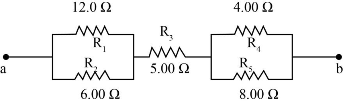
Figure-(1)
Resistors
Write the expression to calculate the equivalent resistance for
Here,
Resistors
Write the expression to calculate the equivalent resistance for
Here,
Write the expression to calculate the equivalent resistance of the circuit.
Here,
Conclusion:
Substitute
Substitute
Substitute
Therefore, the equivalent resistance between points
(b)
The current in each resistor.
(b)
Answer to Problem 17P
The current across the resistor of
Explanation of Solution
Write the expression to calculate the total current.
Here,
Since the resistances
Write the expression to calculate the voltage for resistance
Here,
Since resistors
Write the expression to calculate the voltage for resistance
Here,
Since resistors
Write the expression to calculate the current across resistor
Conclusion:
Substitute
Substitute
Substitute
Substitute
Substitute
Substitute
Substitute
Current across resistor
Therefore, the current across resistor
Want to see more full solutions like this?
Chapter 28 Solutions
PHYSICS:F/SCI...W/MOD..-UPD(LL)W/ACCES


- A lightbulb is connected to a variable power supply. As the potential across the bulb is varied, the resulting current and the filaments temperature are measured. The data are listed in Table P28.38. a. Find R for each entry in Table P28.38, and then plot R as a function of T. b. Assume that room temperature is at 293 K. Find R0 (resistance at room temperature). Comment on your result.arrow_forwardFor the circuit shown in Figure P28.55. the ideal voltmeter reads 6.00 V and the ideal ammeter reads 3.00-k. Find (a) the value of K, (b) the emf of the battery, and (c) the voltage across the 3.00-kft resistor.arrow_forwardFigure P29.45 shows five resistors connected between terminals a and b. a. What is the equivalent resistance of this combination of resistors? b. What is the current through each resistor if a 24.0-V battery is connected across the terminals?arrow_forward
- In the circuit of Figure P28.30, determine (a) the current in each resistor and (b) the potential difference across the 200- resistor.arrow_forwardTwo batteries with e1=3 V and e2=5 V are connected to three resistors of R1= 10 W, R2= 20 W and R3= 30 W as in the circuit in the figure. Find the current values of I1, I2 and I3 through the resistors using Kirchoff's rules. (First write the equations clearly, then find the currents)arrow_forwardIn the figure below, the ideal batteries have emfs ℰ1 = 12 V, ℰ2 = 6.0 V, and the resistors have resistances R1 = 4.0 Ω and R2 = 5.0 Ω. (a) What is the current in the circuit? _________A(b) What is the dissipation rate in resistor 1? _________W(c) What is the dissipation rate in resistor 2? __________W (please show units when you work this out so that I can follow it easier.)arrow_forward
- In the figure the ideal batteries have emfs 1 = 26 V and 2 = 7.0 V and the resistors have resistances R1 = 4.2 Ω and R2 = 8.3 Ω. What are (a) the current, the energy dissipation rate in (b) resistor 1 and (c) resistor 2, and the energy transfer rate in (d) battery 1 and (e) battery 2? Is energy being supplied or absorbed by (f) battery 1 and (g) battery 2?arrow_forwardIn (Figure 1) the battery has emf 43.0 V and negligible internal resistance. R1 = 7.00 Ω . The current through R1 is 2.30 A and the current through R3 = 4.90 AA. (a) What is he resistance R2? (b) What is the resistance R3?arrow_forwardAssume that you have a voltage source of 31 V and three resistors: Resistor A is 9.5 Ω, Resistor B is 4.1 Ω, and Resistor C is 4.1 Ω. Part (a) Assuming that the three resistors are connected in series, what is the voltage drop Resistor B? VB = V Part (b) Assuming that the three resistors are connected in series, what is the voltage drop Resistor C? VC = Varrow_forward
- The power dissipated by a resistor with a resistance of R = 100Ω is P = 2.0 W . What are the current through and the voltage drop across the resistor?arrow_forwardA resistor with R1 = 25.0 Ω is connected to a battery that has negligible internal resistance and electrical energy is dissipated by R1 at a rate of 36.0 W. If a second resistor with R2 = 15.0 Ω is connected in series with R1, what is the total rate at which electrical energy is dissipated by the two resistors?arrow_forwardConsider a resistor made from a hollow cylinder of carbon as shown below. The inner radius of the cylinder is Ri = 0.20 mm and the outer radius is R0 = 0.30 mm . The length of the resistor is L = 0.90 mm . The resistivity of the carbon is ρ = 3.5 × 10⁻⁵ Ω · m . (a) Prove that the resistance perpendicular from the axis is R = ρ 2πLln ( R0 Ri). (b) What is the resistance?arrow_forward
 Physics for Scientists and Engineers: Foundations...PhysicsISBN:9781133939146Author:Katz, Debora M.Publisher:Cengage Learning
 Physics for Scientists and Engineers, Technology ...PhysicsISBN:9781305116399Author:Raymond A. Serway, John W. JewettPublisher:Cengage Learning