Videos
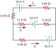
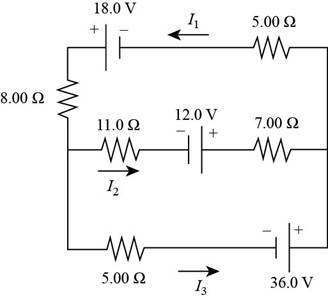
For the circuit shown in Figure P27.22, we wish to find the currents I1, I2, and I3. Use Kirchhoff’s rules to obtain equations for (a) the upper loop, (b) the lower loop, and (c) the junction on the left side. In each case, suppress units for clarity and simplify, combining the terms. (d) Solve the junction equation for I3. (e) Using the equation found in part (d), eliminate I3 from the equation found in part (b). (f) Solve the equations found in parts (a) and (e) simultaneously for the two unknowns I1 and I2. (g) Substitute the answers found in part (f) into the junction equation found in part (d), solving for I3. (h) What is the significance of the negative answer for I2?
Figure P27.22
(a)
Answer to Problem 28.34P
Explanation of Solution
Given info: The figure is given as,

By going counterclockwise around the upper loop and suppressing the unites, the Kirchhoff’s law is applied.
The equation for the upper loop is,
Conclusion:
Therefore, the equation by using Kirchhoff’s rules in the upper loop is
(b)
Answer to Problem 28.34P
Explanation of Solution
Given info: The figure is given as,
By going counterclockwise around the lower loop and suppressing the unites, the Kirchhoff’s law is applied.
The equation for the lower loop is,
Conclusion:
Therefore, the equation by using Kirchhoff’s rules in the lower loop is
(c)
Answer to Problem 28.34P
Explanation of Solution
Given info: The figure is given as,

Apply the junction rule at the node in the left end of the circuit.
The equation for the junction on the left side is,
Conclusion:
Therefore, the equation by using Kirchhoff’s rules at the junction on the left side is
(d)
To solve: The junction on the left side for
Answer to Problem 28.34P
Explanation of Solution
Given info: The figure is given as,

Apply the junction rule at the node in the left end of the circuit.
Rearrange the equation (3) as,
Conclusion:
Therefore, the junction on the left side for
(e)
To eliminate: The current
Answer to Problem 28.34P
Explanation of Solution
Given info: The figure is given as,
The equation for
Substitute
Conclusion:
Therefore, the equation after elimination for
(f)
Answer to Problem 28.34P
Explanation of Solution
Given info: The figure is given as,

Rearrange the equation (4) for
Recall the equation (1).
Substitute
Further, solve,
Thus, the value of
Substitute
Conclusion:
Therefore, the value of
(g)
Answer to Problem 28.34P
Explanation of Solution
Given info: The figure is given as,
The equation for
Substitute
Conclusion:
Therefore, the value of
(h)
Answer to Problem 28.34P
Explanation of Solution
Given info: The figure is given as,
The negative sign in the answer for
Conclusion:
Therefore, the negative sign in the answer for
Want to see more full solutions like this?
Chapter 28 Solutions
Physics For Scientists And Engineers, Technology Update, Loose-leaf Version


- Consider a series RC circuit as in Figure P28.38 for which R = 1.00 M, C = 5.00 F, and = 30.0 V. Find (a) the time constant of the circuit and (b) the maximum charge on the capacitor after the switch is thrown closed. (c) Find the current in the resistor 10.0 s after the switch is closed.arrow_forwardConsider a series RC circuit as in Figure P18.35 for which R = 1.00 M, C = 5.00 F, and = 30.0 V. Find (a) the time constant of the circuit and (b) the maximum charge on the capacitor after the switch is thrown closed. (c) Find the current in the resistor 10.0 s after the switch is closed. Figure P18.35 Problem 35 and 38.arrow_forwardIn the circuit of Figure P27.25, the switch S has been open for a long time. It is then suddenly closed. Take = 10.0 V, R1 = 50.0 k, R2 = 100 k, and C = 10.0 F. Determine the time constant (a) before the switch is closed and (b) after the switch is closed. (c) Let the switch be closed at t = 0. Determine the current in the switch as a function of time. Figure P27.25 Problems 25 and 26.arrow_forward
- Each resistor shown in Figure P29.36 has a resistance of 100.0 . An ideal emf device (120.0 V) is connected to points a and b via two leads (not shown in the figure). Find the current that flows through the emf device.arrow_forwardFigure P29.77 shows a circuit with two batteries and three resistors. a. How much current flows through the 2.00- resistor? b. What is the potential difference between points a and b in the circuit?arrow_forwardThe circuit shown in Figure P28.78 is set up in the laboratory to measure an unknown capacitance C in series with a resistance R = 10.0 M powered by a battery whose emf is 6.19 V. The data given in the table are the measured voltages across the capacitor as a function of lime, where t = 0 represents the instant at which the switch is thrown to position b. (a) Construct a graph of In (/v) versus I and perform a linear least-squares fit to the data, (b) From the slope of your graph, obtain a value for the time constant of the circuit and a value for the capacitance. v(V) t(s) In (/v) 6.19 0 5.56 4.87 4.93 11.1 4.34 19.4 3.72 30.8 3.09 46.6 2.47 67.3 1.83 102.2arrow_forward
- In The circuit given in pic, the current passed through the resistance 1 is i1=2A and theresistance are R1=2.00 Ω, R2=3.00 Ω, R3=2.50 Ω, R4=6.0 Ω, R5=4.00 Ω and R6=3.50 Ω. a) What is the equivalent resistance of the circuit? b) What is the emf of the battery?arrow_forwardConsider the circuit shown below, with a battery of emf E = 20. V, and resistors R1 = 2.0 Ω, R2 = 5.0 Ω, R3 = 4.0 Ω, and R4 = 12 Ω. In this problem, give your answers to two significant figures. a) How much current I2 flows through resistor R2, in amperes? b) How much current flows through resistor R3, in amperes? c) How much current flows through resistor R4, in amperes?arrow_forwardThere is a current of 0.25 A in the circuit of Figure P23.69.a. What is the direction of the current? Explain.b. What is the value of the resistance R?c. What is the power dissipated by R?d. Make a graph of potential versus position, starting from V = 0 V in the lower left corner and proceeding clockwise.See Figure P23.9 for an example.arrow_forward
- The figure below shows a capacitor, with capacitance C = 4.72 µF, and a resistor, with resistance R = 6.48 MΩ, connected in series to a battery, with ε = 26.0 V. The circuit has a switch, which is initially open. (a) What is the circuit's time constant (in seconds)? (b) What is the maximum charge (in µC) on the capacitor after the switch is closed? (c) What is the current (in µA) through the resistor 10.0 s after the switch is closed?arrow_forwardA heart defibrillator being used on a patient has an RC time constant of 9.5 ms due to the resistance of the patient's body and the capacitance of the defibrillator. τ = 9.5 msC = 6.5 μFV = 11.5 kV a) If the defibrillator has an 6.5 μF capacitance, what is the resistance of the path through the patient in kΩ? b) If the initial voltage is 11.5 kV, how long does it take to decline to 6.00 × 10² V in ms?arrow_forward
 Principles of Physics: A Calculus-Based TextPhysicsISBN:9781133104261Author:Raymond A. Serway, John W. JewettPublisher:Cengage Learning
 Physics for Scientists and Engineers: Foundations...PhysicsISBN:9781133939146Author:Katz, Debora M.Publisher:Cengage Learning
 Physics for Scientists and Engineers, Technology ...PhysicsISBN:9781305116399Author:Raymond A. Serway, John W. JewettPublisher:Cengage Learning
 Physics for Scientists and Engineers with Modern ...PhysicsISBN:9781337553292Author:Raymond A. Serway, John W. JewettPublisher:Cengage Learning
 Physics for Scientists and EngineersPhysicsISBN:9781337553278Author:Raymond A. Serway, John W. JewettPublisher:Cengage Learning
 College PhysicsPhysicsISBN:9781285737027Author:Raymond A. Serway, Chris VuillePublisher:Cengage Learning