EBK PHYSICS FOR SCIENTISTS AND ENGINEER
9th Edition
ISBN: 8220100461262
Author: SERWAY
Publisher: Cengage Learning US
expand_more
expand_more
format_list_bulleted
Videos
Textbook Question
Chapter 28, Problem 28.42P
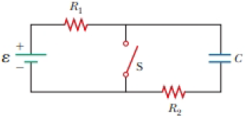
In the circuit of Figure P27.25, the switch S has been open for a long time. It is then suddenly closed. Determine the time constant (a) before the switch is closed and (b) after the switch is closed. (c) Let the switch be closed at t = 0. Determine the current in the switch as a function of time.
Figure P27.25 Problems 25 and 26.
Expert Solution & Answer

Trending nowThis is a popular solution!

Students have asked these similar questions
An uncharged capacitor is connected in series with a resistor, a dc battery and an open switch. At time t = 0 s, the switch is closed. Which of the graphs below best describes the magnitude of the potential difference V across the resistor as a function of time t?
There is a current of 0.25 A in the circuit of Figure P23.69.a. What is the direction of the current? Explain.b. What is the value of the resistance R?c. What is the power dissipated by R?d. Make a graph of potential versus position, starting from V = 0 V in the lower left corner and proceeding clockwise.See Figure P23.9 for an example.
At time t=0, the switch in the circuit shown in the figure is closed. After a sufficiently long time, steady currents I1 ,I2 and I3 flow through resistors R1 ,R2 and R3 , respectively. Determine these three currents.
Chapter 28 Solutions
EBK PHYSICS FOR SCIENTISTS AND ENGINEER
Ch. 28 - To maximize the percentage of the power from the...Ch. 28 - With the switch in the circuit of Figure 27.4a...Ch. 28 - With the switch in the circuit of Figure 27.6a...Ch. 28 - Prob. 28.4QQCh. 28 - Consider the circuit in Figure 27.17 and assume...Ch. 28 - Is a circuit breaker wired (a) in series with the...Ch. 28 - A battery has some internal resistance. (i) Clan...Ch. 28 - The terminals of a battery are connected across...Ch. 28 - When operating on a 120-V circuit, an electric...Ch. 28 - If the terminals of a battery with zero internal...
Ch. 28 - Prob. 28.6OQCh. 28 - What is the time constant of the circuit shown in...Ch. 28 - When resistors with different resistances are...Ch. 28 - When resistors with different resistances are...Ch. 28 - The terminals of a battery are connected across...Ch. 28 - Are the two headlights of a car wired (a) in...Ch. 28 - In the circuit shown in Figure OQ28.12, each...Ch. 28 - Prob. 28.13OQCh. 28 - A circuit consists of three identical lamps...Ch. 28 - A series circuit consists of three identical lamps...Ch. 28 - Suppose a parachutist lands on a high-voltage wire...Ch. 28 - A student claims that the second of two lightbulbs...Ch. 28 - Why is ii possible for a bird to sit on a...Ch. 28 - Given three lightbulbs and a battery, sketch as...Ch. 28 - Prob. 28.5CQCh. 28 - Referring to Figure CQ28.6, describe what happens...Ch. 28 - Prob. 28.7CQCh. 28 - (a) What advantage does 120-V operation offer over...Ch. 28 - Prob. 28.9CQCh. 28 - Prob. 28.10CQCh. 28 - A battery has an emf of 15.0 V. The terminal...Ch. 28 - Two 1.50-V batterieswith their positive terminals...Ch. 28 - An automobile battery has an emf of 12.6 V and 171...Ch. 28 - As in Example 27.2, consider a power supply with...Ch. 28 - Three 100- resistors are connected as shown in...Ch. 28 - Prob. 28.6PCh. 28 - What is the equivalent resistance of the...Ch. 28 - Consider the two circuits shown in Figure P27.5 in...Ch. 28 - Consider the circuit shown in Figure P28.9. Find...Ch. 28 - (a) You need a 45- resistor, but the stockroom has...Ch. 28 - A battery with = 6.00 V and no internal...Ch. 28 - A battery with emf and no internal resistance...Ch. 28 - (a) Kind the equivalent resistance between points...Ch. 28 - (a) When the switch S in the circuit of Figure...Ch. 28 - Prob. 28.15PCh. 28 - Four resistors are connected to a battery as shown...Ch. 28 - Consider die combination of resistors shown in...Ch. 28 - For the purpose of measuring the electric...Ch. 28 - Calculate the power delivered to each resistor in...Ch. 28 - Why is the following situation impossible? A...Ch. 28 - Consider the circuit shown in Figure P28.21 on...Ch. 28 - In Figure P28.22, show how to add just enough...Ch. 28 - The circuit shown in Figure P27.17 is connected...Ch. 28 - For the circuit shown in Figure P28.24, calculate...Ch. 28 - What are the expected readings of (a) the ideal...Ch. 28 - The following equations describe an electric...Ch. 28 - Taking R = 1.00 k and = 250 V in Figure P27.19,...Ch. 28 - You have a faculty position at a community college...Ch. 28 - The ammeter shown in Figure P28.29 reads 2.00 A....Ch. 28 - In the circuit of Figure P28.30, determine (a) the...Ch. 28 - Using Kirchhoffs rules, (a) find (he current in...Ch. 28 - In the circuit of Figure P27.20, the current I1 =...Ch. 28 - In Figure P28.33, find (a) the current in each...Ch. 28 - For the circuit shown in Figure P27.22, we wish to...Ch. 28 - Find the potential difference across each resistor...Ch. 28 - (a) Can the circuit shown in Figure P27.21 be...Ch. 28 - An uncharged capacitor and a resistor are...Ch. 28 - Consider a series RC circuit as in Figure P28.38...Ch. 28 - A 2.00-nF capacitor with an initial charge of 5.10...Ch. 28 - A 10.0-F capacitor is charged by a 10.0-V battery...Ch. 28 - In the circuit of Figure P27.25, the switch S has...Ch. 28 - In the circuit of Figure P27.25, the switch S has...Ch. 28 - The circuit in Figure P28.43 has been connected...Ch. 28 - Show that the integral 0e2t/RCdtin Example 27.11...Ch. 28 - A charged capacitor is connected to a resistor and...Ch. 28 - Prob. 28.46PCh. 28 - Prob. 28.47PCh. 28 - Turn on your desk lamp. Pick up the cord, with...Ch. 28 - Assume you have a battery of emf and three...Ch. 28 - Find the equivalent resistance between points a...Ch. 28 - Four 1.50-V AA batteries in series are used to...Ch. 28 - Four resistors are connected in parallel across a...Ch. 28 - The circuit in Figure P27.35 has been connected...Ch. 28 - The circuit in Figure P27.34a consists of three...Ch. 28 - For the circuit shown in Figure P28.55. the ideal...Ch. 28 - The resistance between terminals a and b in Figure...Ch. 28 - (a) Calculate the potential difference between...Ch. 28 - Why is the following situation impossible? A...Ch. 28 - A rechargeable battery has an emf of 13.2 V and an...Ch. 28 - Find (a) the equivalent resistance of the circuit...Ch. 28 - When two unknown resistors are connected in series...Ch. 28 - When two unknown resistors are connected in series...Ch. 28 - The- pair of capacitors in Figure P28.63 are fully...Ch. 28 - A power supply has an open-circuit voltage of 40.0...Ch. 28 - The circuit in Figure P27.41 contains two...Ch. 28 - Two resistors R1 and R2 are in parallel with each...Ch. 28 - Prob. 28.67APCh. 28 - A battery is used to charge a capacitor through a...Ch. 28 - A young man owns a canister vacuum cleaner marked...Ch. 28 - (a) Determine the equilibrium charge on the...Ch. 28 - Switch S shown in Figure P28.71 has been closed...Ch. 28 - Three identical 60.0-W, 120-V lightbulbs are...Ch. 28 - A regular tetrahedron is a pyramid with a...Ch. 28 - An ideal voltmeter connected across a certain...Ch. 28 - In Figure P27.47, suppose the switch has been...Ch. 28 - Figure P27.48 shows a circuit model for the...Ch. 28 - The student engineer of a campus radio station...Ch. 28 - The circuit shown in Figure P28.78 is set up in...Ch. 28 - An electric teakettle has a multiposition switch...Ch. 28 - A voltage V is applied to a series configuration...Ch. 28 - In places such as hospital operating rooms or...Ch. 28 - The switch in Figure P27.51a closes when Vc23Vand...Ch. 28 - The resistor R in Figure P28.83 receives 20.0 W of...
Knowledge Booster


Learn more about
Need a deep-dive on the concept behind this application? Look no further. Learn more about this topic, physics and related others by exploring similar questions and additional content below.Similar questions
- In the circuit of Figure P27.25, the switch S has been open for a long time. It is then suddenly closed. Take = 10.0 V, R1 = 50.0 k, R2 = 100 k, and C = 10.0 F. Determine the time constant (a) before the switch is closed and (b) after the switch is closed. (c) Let the switch be closed at t = 0. Determine the current in the switch as a function of time. Figure P27.25 Problems 25 and 26.arrow_forwardIn the circuit of Figure P21.57, the switch S has been open for a long time. It is then suddenly closed. Take = 10.0 V, R1 = 50.0 k, R2 = 100 k, and C = 10.0 F. Determine the time constant (a) before the switch is closed and (b) after the switch is closed. (c) Let the switch be closed at t = 0. Determine the current in the switch as a function of time.arrow_forwardEach of the three situations in Figure P32.68 shows a resistor in a circuit in which currents are induced. Using Lenzs law, determine whether the current in each situation is from a to b or from b to a. a. If the current I in the wire in Figure P32.68A is increased from zero to I, what is the direction of the current induced across the resistor R? b. The switch in Figure P32.68B is initially closed and is thrown open at t = 0. What is the direction of the current induced across the resistor R immediately afterward? c. A bar magnet is brought close to the circuit shown in Figure P32.68C. What is the direction of the current induced across the resistor R?arrow_forward
- You connect a battery, resistor, and capacitor as in (Figure 1), where R = 14.0 Ω and C = 3.00 ×10^-6 F. The switch S is closed at t = 0. When the current in the circuit has magnitude 3.00 A, the charge on the capacitor is 40.0 × 10^−6 C. At what time t after the switch is closed is the charge on the capacitor equal to 40.0 x 10^-6 C? When the current has magnitude 3.00 A, at what rate is energy being stored in the capacitor?arrow_forwardChapter 32, Problem 018 Your answer is partially correct. Try again. The circuit in the figure consists of switch S, a 4.50 V ideal battery, a 35.0 M2 resistor, and an airfilled capacitor. The capacitor has parallel circular plates of radius 5.10 cm, separated by 1.50 mm. At time t = 0, switch S is closed to begin charging the capacitor. The electric field between the plates is uniform. At t = 160 µs, what is the magnitude of the magnetic field within the capacitor, at radial distance 3.30 cm? C S R Number Units T. Use correct number of significant digits; the tolerance is +/-1 in the 3rd significant digitarrow_forwardChapter 32, Problem 018 Your answer is partially correct. Try again. The circuit in the figure consists of switch S, a 4.50 V ideal battery, a 35.0 M2 resistor, and an airfilled capacitor. The capacitor has parallel circular plates of radius 5.10 cm, separated by 1.50 mm. At time t = 0, switch S is closed to begin charging the capacitor. The electric field between the plates is uniform. At t = 160 µs, what is the magnitude of the magnetic field within the capacitor, at radial distance 3.30 cm? S R Number Units Use correct number of significant digits; the tolerance is +/-1 in the 3rd significant digitarrow_forward
- Switch S shown in Figure P28.71 has been closed for a long lime, and the electric circuit carries a constant current. Take C1 = 3.00 μF, C2 = 6.00 μF, R1 = 4.00 kΩ, and R2 , = 7.00 kΩ. The power delivered to R2 , is 2.40 W. (a) Find the charge on C1 . (b) Now the switch is opened. After many milliseconds, by how much has the charge on C2 changed?arrow_forwardThe capacitor in the circuit shown below is initially uncharged. The switch is closed at t = 0 s. AV battery = 30 V, C = 3.0 F, and R = 2.0 2. At sometime after the switch is closed, the current in the circuit is measured to be 9.3 A. What is the charge on the capacitor at this time, in Coulomb? Your answer needs to have 2 significant figures, including the negative sign in your answer if needed. Do not include the positive sign if the answer is positive. No unit is needed in your answer, it is already given in the question statement.arrow_forwardChapter 30, Problem 054 In the figure, ε = 118 V, R₁ = 14.9 №, R₂ = 21.3 N, R3 = 35.8 №, and L= 1.90 H. Immediately after switch S is closed, what are (a) i₁ and (b) i₂? (Let currents in the indicated directions have positive values and currents in the opposite directions have negative values.) A long time later, what are (c) ₁ and (d) i2? The switch is then reopened. Just then, what are (e) ₁ and (f) i₂? A long time later, what are (g) ₁ and (h) i₂? www R₁ R$ R₂ Larrow_forward
- 78. A In the RC circuit shown in Figure FOR P29.78, an ideal battery with emf CHEST E and internal resistance r is con- no bruta 101 nected to capacitor C. The switch OTU S is initially open and the capacitor noilor is uncharged. At t = 0, the switch 20 is closed. srit word or abs gnizu dmod odi unslaviups 15/vol S ε reutills α.— himmisiob of W+0.000 21 d I f es bspar 21251 in 152 s ban a. Determine the charge q on the capacitor at time t. Tro b. Find the current in the branch b-e at time t. What is the the 1569 € 210121231 910 current as t goes to infinity? 100% www r b e digi Div ST 0 R + 20, 251 29gnado 101000 9.00 V bilov adi tol noia201qzs FIGURE P29.77 5.00 265 Ω www STEVO R www.c FIGURE P29.78 poses. 79. N A 12.0-V battery is used to cho **** 21 memisa M.ET C - - с d b bes 19lbbigarrow_forwardConsider the circuit below. The capacitor has a capacitance of 11 mF and starts out uncharged. The switch is closed at time t = 0. @ 2 W V = 12 V F2 R₁ = 20 Diagram Description R₂=402 # 3 a. At time t= 0 (immediately after the switch is closed), what is battery? Hint for (a) At time t= 0, the current from the battery is b. A long time after the switch is closed (and capacitor is fully charged), what is the current flowing out from the battery? Hint for (b) 80 F3 R₂ = 30 A long time after the switch is closed, the current from the battery is c. What is the charge on the capacitor a long time after the switch is closed? Hint for (c) The charge on the capacitor a long time after the switch is closed is E m $ R₁ = 30 F4 R % 5 current flowing out from the F5 T 6 F6 Y A. mC. & 7 AA F7 U * 00 8 DII FB ( 9 8 F9arrow_forwardCopper has a resistivity of ρc = 1.72 × 10⁻⁸ Ω⋅m. An extension cord made of copper is connected to a DC electric motor which requires a current of at least Imin = 4.5 A in order to operate. The cord is connected to a V = 151 V source. A. Input an expression for the maximum ratio of length to cross-sectional area, γ, the cord can have if the motor is to operate. B. What is the ratio numerically in 1/m? C. Experimentally, it is found that the maximum length the cord can be is Lmax = 30 m. What is the wire's minimum diameter, Dmin, in meters?arrow_forward
arrow_back_ios
arrow_forward_ios
Recommended textbooks for you
 Physics for Scientists and EngineersPhysicsISBN:9781337553278Author:Raymond A. Serway, John W. JewettPublisher:Cengage Learning
 Physics for Scientists and Engineers with Modern ...PhysicsISBN:9781337553292Author:Raymond A. Serway, John W. JewettPublisher:Cengage Learning
 Principles of Physics: A Calculus-Based TextPhysicsISBN:9781133104261Author:Raymond A. Serway, John W. JewettPublisher:Cengage Learning
 Physics for Scientists and Engineers: Foundations...PhysicsISBN:9781133939146Author:Katz, Debora M.Publisher:Cengage Learning
Physics for Scientists and Engineers
Physics
ISBN:9781337553278
Author:Raymond A. Serway, John W. Jewett
Publisher:Cengage Learning
Physics for Scientists and Engineers with Modern ...
Physics
ISBN:9781337553292
Author:Raymond A. Serway, John W. Jewett
Publisher:Cengage Learning
Principles of Physics: A Calculus-Based Text
Physics
ISBN:9781133104261
Author:Raymond A. Serway, John W. Jewett
Publisher:Cengage Learning
Physics for Scientists and Engineers: Foundations...
Physics
ISBN:9781133939146
Author:Katz, Debora M.
Publisher:Cengage Learning
What is Electromagnetic Induction? | Faraday's Laws and Lenz Law | iKen | iKen Edu | iKen App; Author: Iken Edu;https://www.youtube.com/watch?v=3HyORmBip-w;License: Standard YouTube License, CC-BY