
EBK PHYSICS FOR SCIENTISTS AND ENGINEER
9th Edition
ISBN: 8220100663987
Author: Jewett
Publisher: Cengage Learning US
expand_more
expand_more
format_list_bulleted
Videos
Textbook Question
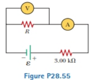
Chapter 28, Problem 28.55AP
For the circuit shown in Figure P28.55. the ideal voltmeter reads 6.00 V and the ideal ammeter reads 3.00-kΩ. Find (a) the value of K, (b) the emf of the battery, and (c) the voltage across the 3.00-kft resistor.
Expert Solution & Answer

Trending nowThis is a popular solution!

Students have asked these similar questions
What are the expected readings of (a) the ideal ammeter and (b) the ideal voltmeter in Figure?
24.0 V
4.00 A
R
4.00 A
Figure N
8. Consider the circuit shown in Figure b. The terminal voltage of the 24.0 V
battery is 21.2 V. What is
a) the internal resistance r of the battery; b) the resistance R of the circuit
resistor???
An electric circuit consists of two emf sources with negligible internal resistance, three resistors, and a voltage meter (V) as represented in the picture above. The voltage meter has infinite resistance and displays the voltage V_ab= V_a - V_b between the points a and b in the circuit. What is the magnitude and direction (towards or away from point b) of the current in the 9.00 ohm resistor ? What is the voltage
difference V_ab the voltmeter displays?
Chapter 28 Solutions
EBK PHYSICS FOR SCIENTISTS AND ENGINEER
Ch. 28 - To maximize the percentage of the power from the...Ch. 28 - With the switch in the circuit of Figure 27.4a...Ch. 28 - With the switch in the circuit of Figure 27.6a...Ch. 28 - Prob. 28.4QQCh. 28 - Consider the circuit in Figure 27.17 and assume...Ch. 28 - Is a circuit breaker wired (a) in series with the...Ch. 28 - A battery has some internal resistance. (i) Clan...Ch. 28 - The terminals of a battery are connected across...Ch. 28 - When operating on a 120-V circuit, an electric...Ch. 28 - If the terminals of a battery with zero internal...
Ch. 28 - Prob. 28.6OQCh. 28 - What is the time constant of the circuit shown in...Ch. 28 - When resistors with different resistances are...Ch. 28 - When resistors with different resistances are...Ch. 28 - The terminals of a battery are connected across...Ch. 28 - Are the two headlights of a car wired (a) in...Ch. 28 - In the circuit shown in Figure OQ28.12, each...Ch. 28 - Prob. 28.13OQCh. 28 - A circuit consists of three identical lamps...Ch. 28 - A series circuit consists of three identical lamps...Ch. 28 - Suppose a parachutist lands on a high-voltage wire...Ch. 28 - A student claims that the second of two lightbulbs...Ch. 28 - Why is ii possible for a bird to sit on a...Ch. 28 - Given three lightbulbs and a battery, sketch as...Ch. 28 - Prob. 28.5CQCh. 28 - Referring to Figure CQ28.6, describe what happens...Ch. 28 - Prob. 28.7CQCh. 28 - (a) What advantage does 120-V operation offer over...Ch. 28 - Prob. 28.9CQCh. 28 - Prob. 28.10CQCh. 28 - A battery has an emf of 15.0 V. The terminal...Ch. 28 - Two 1.50-V batterieswith their positive terminals...Ch. 28 - An automobile battery has an emf of 12.6 V and 171...Ch. 28 - As in Example 27.2, consider a power supply with...Ch. 28 - Three 100- resistors are connected as shown in...Ch. 28 - Prob. 28.6PCh. 28 - What is the equivalent resistance of the...Ch. 28 - Consider the two circuits shown in Figure P27.5 in...Ch. 28 - Consider the circuit shown in Figure P28.9. Find...Ch. 28 - (a) You need a 45- resistor, but the stockroom has...Ch. 28 - A battery with = 6.00 V and no internal...Ch. 28 - A battery with emf and no internal resistance...Ch. 28 - (a) Kind the equivalent resistance between points...Ch. 28 - (a) When the switch S in the circuit of Figure...Ch. 28 - Prob. 28.15PCh. 28 - Four resistors are connected to a battery as shown...Ch. 28 - Consider die combination of resistors shown in...Ch. 28 - For the purpose of measuring the electric...Ch. 28 - Calculate the power delivered to each resistor in...Ch. 28 - Why is the following situation impossible? A...Ch. 28 - Consider the circuit shown in Figure P28.21 on...Ch. 28 - In Figure P28.22, show how to add just enough...Ch. 28 - The circuit shown in Figure P27.17 is connected...Ch. 28 - For the circuit shown in Figure P28.24, calculate...Ch. 28 - What are the expected readings of (a) the ideal...Ch. 28 - The following equations describe an electric...Ch. 28 - Taking R = 1.00 k and = 250 V in Figure P27.19,...Ch. 28 - You have a faculty position at a community college...Ch. 28 - The ammeter shown in Figure P28.29 reads 2.00 A....Ch. 28 - In the circuit of Figure P28.30, determine (a) the...Ch. 28 - Using Kirchhoffs rules, (a) find (he current in...Ch. 28 - In the circuit of Figure P27.20, the current I1 =...Ch. 28 - In Figure P28.33, find (a) the current in each...Ch. 28 - For the circuit shown in Figure P27.22, we wish to...Ch. 28 - Find the potential difference across each resistor...Ch. 28 - (a) Can the circuit shown in Figure P27.21 be...Ch. 28 - An uncharged capacitor and a resistor are...Ch. 28 - Consider a series RC circuit as in Figure P28.38...Ch. 28 - A 2.00-nF capacitor with an initial charge of 5.10...Ch. 28 - A 10.0-F capacitor is charged by a 10.0-V battery...Ch. 28 - In the circuit of Figure P27.25, the switch S has...Ch. 28 - In the circuit of Figure P27.25, the switch S has...Ch. 28 - The circuit in Figure P28.43 has been connected...Ch. 28 - Show that the integral 0e2t/RCdtin Example 27.11...Ch. 28 - A charged capacitor is connected to a resistor and...Ch. 28 - Prob. 28.46PCh. 28 - Prob. 28.47PCh. 28 - Turn on your desk lamp. Pick up the cord, with...Ch. 28 - Assume you have a battery of emf and three...Ch. 28 - Find the equivalent resistance between points a...Ch. 28 - Four 1.50-V AA batteries in series are used to...Ch. 28 - Four resistors are connected in parallel across a...Ch. 28 - The circuit in Figure P27.35 has been connected...Ch. 28 - The circuit in Figure P27.34a consists of three...Ch. 28 - For the circuit shown in Figure P28.55. the ideal...Ch. 28 - The resistance between terminals a and b in Figure...Ch. 28 - (a) Calculate the potential difference between...Ch. 28 - Why is the following situation impossible? A...Ch. 28 - A rechargeable battery has an emf of 13.2 V and an...Ch. 28 - Find (a) the equivalent resistance of the circuit...Ch. 28 - When two unknown resistors are connected in series...Ch. 28 - When two unknown resistors are connected in series...Ch. 28 - The- pair of capacitors in Figure P28.63 are fully...Ch. 28 - A power supply has an open-circuit voltage of 40.0...Ch. 28 - The circuit in Figure P27.41 contains two...Ch. 28 - Two resistors R1 and R2 are in parallel with each...Ch. 28 - Prob. 28.67APCh. 28 - A battery is used to charge a capacitor through a...Ch. 28 - A young man owns a canister vacuum cleaner marked...Ch. 28 - (a) Determine the equilibrium charge on the...Ch. 28 - Switch S shown in Figure P28.71 has been closed...Ch. 28 - Three identical 60.0-W, 120-V lightbulbs are...Ch. 28 - A regular tetrahedron is a pyramid with a...Ch. 28 - An ideal voltmeter connected across a certain...Ch. 28 - In Figure P27.47, suppose the switch has been...Ch. 28 - Figure P27.48 shows a circuit model for the...Ch. 28 - The student engineer of a campus radio station...Ch. 28 - The circuit shown in Figure P28.78 is set up in...Ch. 28 - An electric teakettle has a multiposition switch...Ch. 28 - A voltage V is applied to a series configuration...Ch. 28 - In places such as hospital operating rooms or...Ch. 28 - The switch in Figure P27.51a closes when Vc23Vand...Ch. 28 - The resistor R in Figure P28.83 receives 20.0 W of...
Knowledge Booster


Learn more about
Need a deep-dive on the concept behind this application? Look no further. Learn more about this topic, physics and related others by exploring similar questions and additional content below.Similar questions
- Consider the circuit shown in Figure P28.21 on page 860. (a) Find the voltage across the 3.00-0 resistor, (b) Find the current in the 3.00-12 resistor.arrow_forwardConsider a series RC circuit as in Figure P28.38 for which R = 1.00 M, C = 5.00 F, and = 30.0 V. Find (a) the time constant of the circuit and (b) the maximum charge on the capacitor after the switch is thrown closed. (c) Find the current in the resistor 10.0 s after the switch is closed.arrow_forwardThe emf source, E. of the circuit shown in the figure has negligible internal resistance. The resistors have resistances R= 6.62 and R,=4.92. The capacitor has a capacitance C 13.4 uF When the capacitor is fully charged, the magnitude of the charge on its plates is Q 17.1 uC. What is E in units of Volts? R2 O 4.4 O 2.2 R1 O 3.1 O 0.22 O 1.1arrow_forward
- On a cold day a battery has a terminal voltage of V₁ = 12.3 V and an internal resistance of r₁ = 0.0065 92. On a warm day the battery has a terminal voltage of V₂ = 11.64 V and an internal resistance of r2 = 0.028 2. The device it powers draws the same current at both temperatures. Assume the emf of the battery does not depend on temperature. Enter an expression for the current, I, in terms of the given quantities. Calculate the current, I, in amperes. What is the battery's emf, in volts?arrow_forward2o2 3052 352 552 652 2A A. The power dissipated in the 3 Ohms resistor is W. B. The total voltage is V. C. The power dissipated in the 5 Ohms resistor is W. Round all answers to whole numbers.arrow_forwardBased on the plot, what is the most probable value of the capacitance of the capacitor in the circuit (in µF) A. 10 B. 50 C. 25 D. 70 E. 140arrow_forward
- A battery has an emf of ε = 19 V, an internal resistance r = 28 22, and is connected to a resistor of R = 75 22. Express the current I through the circuit in terms of ε, r and R. Calculate the numerical value of I in A. Express the terminal voltage 4V of the battery in terms of I and R. Calculate the numerical value of 4V in V.arrow_forwardConsider the circuit shown in Figure. The emf source has negligible internal resistance. The resistors have resistances R1= 6Ω and R2= 4Ω. The capacitor has capacitance C=9 μF. When the capacitor is fully charged, the magnitude of the charge on its plates is Q=36. Calculate the emf ε.arrow_forwardThe shown circuit is connected for long time. If C=24 µF and &=2.6 V, then find the charge on the capacitor (in µC).arrow_forward
- Find (a) the equivalent resistance of the circuit in Fig- ure P28.60, (b) the potential difference across each resistor, (c) each current indicated in Figure P28.60, and (d) the power delivered to each resistor. 6.00 Ω 2.40 Ω I, 15.0 V 6.00 N 6.00 N d 6.00 N 9.00 Ω Figure P28.60arrow_forwardConsider the circuit shown in the figure below. (Let R, 3.00 Ω, R, 3.00 0, and E = 9.00 V.) 10.0 N R2 5.00 N 2.00 N R (a) Find the voltage across R,. V (b) Find the current in R,. Aarrow_forwardQ1(a) For the dc network shown in Figure Q1 (a), calculate the following: i. The total resistance Rr as seen by the source i. The total current I i. The voltage across the resistance R4 R3 20 + I R: R4 8Ω V. R5 E 24V 120 Rs 12Ω Figure Q1 (a)arrow_forward
arrow_back_ios
SEE MORE QUESTIONS
arrow_forward_ios
Recommended textbooks for you
 Physics for Scientists and Engineers, Technology ...PhysicsISBN:9781305116399Author:Raymond A. Serway, John W. JewettPublisher:Cengage Learning
 Physics for Scientists and Engineers: Foundations...PhysicsISBN:9781133939146Author:Katz, Debora M.Publisher:Cengage Learning
Physics for Scientists and Engineers, Technology ...
Physics
ISBN:9781305116399
Author:Raymond A. Serway, John W. Jewett
Publisher:Cengage Learning
Physics for Scientists and Engineers: Foundations...
Physics
ISBN:9781133939146
Author:Katz, Debora M.
Publisher:Cengage Learning
How To Solve Any Resistors In Series and Parallel Combination Circuit Problems in Physics; Author: The Organic Chemistry Tutor;https://www.youtube.com/watch?v=eFlJy0cPbsY;License: Standard YouTube License, CC-BY