PHYSICS 1250 PACKAGE >CI<
9th Edition
ISBN: 9781305000988
Author: SERWAY
Publisher: CENGAGE LEARNING (CUSTOM)
expand_more
expand_more
format_list_bulleted
Videos
Textbook Question
thumb_up100%
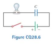
Chapter 28, Problem 28.6CQ
Referring to Figure CQ28.6, describe what happens to the lightbulb after the switch is closed. Assume the capacitor has a large capacitance and is initially uncharged. Also assume the light illuminates when connected directly across the battery terminals.
Expert Solution & Answer

Trending nowThis is a popular solution!

Students have asked these similar questions
A parallel plate capacitor has an air-filled gap. It is attached an EMF and charged it to charge Qo and voltage difference ΔVco. Two different experiments are done.
Case A: The gap between the capacitor plates is then filled with Teflon with the capacitor still connected directly across the terminals of the EMF.
Case B: The capacitor is disconnected from the EMF first before the gap in between the plates is then filled with Teflon.
Which statement is true after the Teflon is inserted into the gap?
1.) In case A, ΔVc is unchanged but Q increases to keep the net E field between the plates unchanged. In case B, Q is unchanged but ΔVc decreases due to a smaller net E field between the plates.
2.) In case A, Q is unchanged but ΔVc decreases due to a smaller net E field between the plates. In case B, ΔVc is unchanged but Q increases to keep the net E field between the plates unchanged.
3.) In case A, Q is unchanged but ΔVc increases due to a larger net E field between the plates. In case…
Q (t) = 3e-0.7t
sin() + 0.01 sin(4t) - 0.02 cos(4t)
The function Q defined above models the electric charge, measured in coulombs, inside a lightbulb t seconds after it is turned on. Which of the
following presents the method for finding the instantaneous rate of change of the lightbulb's electric charge, in coulombs per second, at time t = 4?
Q" (4) = -0.213
A
B
C
D
Q'(4) = -0.171
Q(4) Q (0)
4-0
= 0.053
Q (4) = 0.194
In the figure, suppose the switch has been closed for a length of time sufficiently long for the capacitor to become fully charged. For this circuit, R1 = 12.0 kΩ, R2 = 15.0 kΩ, R3 = 3.000 kΩ, C = 10.0 μF , and emf = 9.00 V. Find (d) the potential differance across R2. (e) the charge on the capacitor.
Chapter 28 Solutions
PHYSICS 1250 PACKAGE >CI<
Ch. 28 - To maximize the percentage of the power from the...Ch. 28 - With the switch in the circuit of Figure 27.4a...Ch. 28 - With the switch in the circuit of Figure 27.6a...Ch. 28 - Prob. 28.4QQCh. 28 - Consider the circuit in Figure 27.17 and assume...Ch. 28 - Is a circuit breaker wired (a) in series with the...Ch. 28 - A battery has some internal resistance. (i) Clan...Ch. 28 - The terminals of a battery are connected across...Ch. 28 - When operating on a 120-V circuit, an electric...Ch. 28 - If the terminals of a battery with zero internal...
Ch. 28 - Prob. 28.6OQCh. 28 - What is the time constant of the circuit shown in...Ch. 28 - When resistors with different resistances are...Ch. 28 - When resistors with different resistances are...Ch. 28 - The terminals of a battery are connected across...Ch. 28 - Are the two headlights of a car wired (a) in...Ch. 28 - In the circuit shown in Figure OQ28.12, each...Ch. 28 - Prob. 28.13OQCh. 28 - A circuit consists of three identical lamps...Ch. 28 - A series circuit consists of three identical lamps...Ch. 28 - Suppose a parachutist lands on a high-voltage wire...Ch. 28 - A student claims that the second of two lightbulbs...Ch. 28 - Why is ii possible for a bird to sit on a...Ch. 28 - Given three lightbulbs and a battery, sketch as...Ch. 28 - Prob. 28.5CQCh. 28 - Referring to Figure CQ28.6, describe what happens...Ch. 28 - Prob. 28.7CQCh. 28 - (a) What advantage does 120-V operation offer over...Ch. 28 - Prob. 28.9CQCh. 28 - Prob. 28.10CQCh. 28 - A battery has an emf of 15.0 V. The terminal...Ch. 28 - Two 1.50-V batterieswith their positive terminals...Ch. 28 - An automobile battery has an emf of 12.6 V and 171...Ch. 28 - As in Example 27.2, consider a power supply with...Ch. 28 - Three 100- resistors are connected as shown in...Ch. 28 - Prob. 28.6PCh. 28 - What is the equivalent resistance of the...Ch. 28 - Consider the two circuits shown in Figure P27.5 in...Ch. 28 - Consider the circuit shown in Figure P28.9. Find...Ch. 28 - (a) You need a 45- resistor, but the stockroom has...Ch. 28 - A battery with = 6.00 V and no internal...Ch. 28 - A battery with emf and no internal resistance...Ch. 28 - (a) Kind the equivalent resistance between points...Ch. 28 - (a) When the switch S in the circuit of Figure...Ch. 28 - Prob. 28.15PCh. 28 - Four resistors are connected to a battery as shown...Ch. 28 - Consider die combination of resistors shown in...Ch. 28 - For the purpose of measuring the electric...Ch. 28 - Calculate the power delivered to each resistor in...Ch. 28 - Why is the following situation impossible? A...Ch. 28 - Consider the circuit shown in Figure P28.21 on...Ch. 28 - In Figure P28.22, show how to add just enough...Ch. 28 - The circuit shown in Figure P27.17 is connected...Ch. 28 - For the circuit shown in Figure P28.24, calculate...Ch. 28 - What are the expected readings of (a) the ideal...Ch. 28 - The following equations describe an electric...Ch. 28 - Taking R = 1.00 k and = 250 V in Figure P27.19,...Ch. 28 - You have a faculty position at a community college...Ch. 28 - The ammeter shown in Figure P28.29 reads 2.00 A....Ch. 28 - In the circuit of Figure P28.30, determine (a) the...Ch. 28 - Using Kirchhoffs rules, (a) find (he current in...Ch. 28 - In the circuit of Figure P27.20, the current I1 =...Ch. 28 - In Figure P28.33, find (a) the current in each...Ch. 28 - For the circuit shown in Figure P27.22, we wish to...Ch. 28 - Find the potential difference across each resistor...Ch. 28 - (a) Can the circuit shown in Figure P27.21 be...Ch. 28 - An uncharged capacitor and a resistor are...Ch. 28 - Consider a series RC circuit as in Figure P28.38...Ch. 28 - A 2.00-nF capacitor with an initial charge of 5.10...Ch. 28 - A 10.0-F capacitor is charged by a 10.0-V battery...Ch. 28 - In the circuit of Figure P27.25, the switch S has...Ch. 28 - In the circuit of Figure P27.25, the switch S has...Ch. 28 - The circuit in Figure P28.43 has been connected...Ch. 28 - Show that the integral 0e2t/RCdtin Example 27.11...Ch. 28 - A charged capacitor is connected to a resistor and...Ch. 28 - Prob. 28.46PCh. 28 - Prob. 28.47PCh. 28 - Turn on your desk lamp. Pick up the cord, with...Ch. 28 - Assume you have a battery of emf and three...Ch. 28 - Find the equivalent resistance between points a...Ch. 28 - Four 1.50-V AA batteries in series are used to...Ch. 28 - Four resistors are connected in parallel across a...Ch. 28 - The circuit in Figure P27.35 has been connected...Ch. 28 - The circuit in Figure P27.34a consists of three...Ch. 28 - For the circuit shown in Figure P28.55. the ideal...Ch. 28 - The resistance between terminals a and b in Figure...Ch. 28 - (a) Calculate the potential difference between...Ch. 28 - Why is the following situation impossible? A...Ch. 28 - A rechargeable battery has an emf of 13.2 V and an...Ch. 28 - Find (a) the equivalent resistance of the circuit...Ch. 28 - When two unknown resistors are connected in series...Ch. 28 - When two unknown resistors are connected in series...Ch. 28 - The- pair of capacitors in Figure P28.63 are fully...Ch. 28 - A power supply has an open-circuit voltage of 40.0...Ch. 28 - The circuit in Figure P27.41 contains two...Ch. 28 - Two resistors R1 and R2 are in parallel with each...Ch. 28 - Prob. 28.67APCh. 28 - A battery is used to charge a capacitor through a...Ch. 28 - A young man owns a canister vacuum cleaner marked...Ch. 28 - (a) Determine the equilibrium charge on the...Ch. 28 - Switch S shown in Figure P28.71 has been closed...Ch. 28 - Three identical 60.0-W, 120-V lightbulbs are...Ch. 28 - A regular tetrahedron is a pyramid with a...Ch. 28 - An ideal voltmeter connected across a certain...Ch. 28 - In Figure P27.47, suppose the switch has been...Ch. 28 - Figure P27.48 shows a circuit model for the...Ch. 28 - The student engineer of a campus radio station...Ch. 28 - The circuit shown in Figure P28.78 is set up in...Ch. 28 - An electric teakettle has a multiposition switch...Ch. 28 - A voltage V is applied to a series configuration...Ch. 28 - In places such as hospital operating rooms or...Ch. 28 - The switch in Figure P27.51a closes when Vc23Vand...Ch. 28 - The resistor R in Figure P28.83 receives 20.0 W of...
Knowledge Booster


Learn more about
Need a deep-dive on the concept behind this application? Look no further. Learn more about this topic, physics and related others by exploring similar questions and additional content below.Similar questions
- A parallel plate capacitor has surface dimension of 40.0 cm x 20.0 cm. The capacitor is connected to a dc power supply of 50.0 V and a material with = 200 is inserted in between the plates. If the capacitance of the capacitor is 18 F, find a. the pate separation, d in meterb. the energy density of this capacitor, u in Joule per cubic meterarrow_forwardYou are working as a demonstration assistant for a physicsprofessor. He shows you the circuit in Figure P31.14, whichhe wants you to build for an upcoming class. The lightbulbis a household incandescent bulb that receives energy at therate of 40.0 W when operating at 120 V. It has a resistanceR1, which, for simplicity, we will assume is constant at alloperating voltages. The battery in the circuit has an emf of12.0 V. When the switch has been closed for a long time, thebulb glows dimly, since it is powered by only 12.0 V. Whenthe switch is opened, however, the bulb flashes brightly andthen gradually dims to darkness. Your professor wants youto determine two values: (a) the resistance R2 that is necessaryfor the bulb to initially flash, when the switch is opened,at the same brightness it would have if plugged into a 120-Vsocket; (b) the inductance L necessary to keep the currentin the lightbulb above 50.0% of its value when the switchis opened, for a time interval of 2.00 s after it is…arrow_forwardYou are working as a demonstration assistant for a physics professor. He shows you the circuit in Figure P31.14, which he wants you to build for an upcoming class. The lightbulb is a household incandescent bulb that receives energy at the rate of 40.0 W when operating at 120 V. It has a resistance Ry, which, for simplicity, we will assume is constant at all operating voltages. The battery in the circuit has an emf of 12.0 V. When the switch has been closed for a long time, the bulb glows dimly, since it is powered by only 12.0 V. When the switch is opened, however, the bulb flashes brightly and then gradually dims to darkness. Your professor wants you to determine two values: (a) the resistance R, that is neces- sary for the bulb to initially flash, when the switch is opened, at the same brightness it would have if plugged into a 120-V socket; (b) the inductance L necessary to keep the current in the lightbulb above 50.0% of its value when the switch is opened, for a time interval of…arrow_forward
- Problem 8: A capacitor has a potential difference of Vo = 370 V between the plates. When the switch S is closed, it is discharged through a resistor of R = 10.5 k2. At time t = 10 seconds after the switch is closed, the potential difference between the capacitor plates equals Vc = 1.0 V. S Randomized Variables Vo = 370 V R = 10.5 k2 Part (a) Calculate the capacitance of the capacitor in farads. Numeric : A numeric value is expected and not an expression. C = Part (b) Calculate the maximum current Imax that passes through the resistor, in Amperes. Numeric : A numeric value is expected and not an expression. Imax = Part (c) Calculate the current I at time t, in Amperes. Numeric : A numeric value is expected and not an expression. I =arrow_forwardProblem #2: Maxwell's Equations. Consider the RC circuit shown. It consists of: an ideal 18 V battery, E a 30 resistor, and a 15 mF capacitor. R The capacitor consists of two circular plates separated by a small distance. Each plate has radius R € 0.46 m. The capacitor is initially uncharged. GH = At time t = 0, the switch is closed. с 3. How fast is the electric flux between the capacitor plates changing at the instant the switch is closed? S 4. When the current through the resistor is 0.40 A, what is the magnetic field at point H, a distance of 0.35 m from the center of the capacitor?arrow_forwardA capacitor, C'is connected across an emf given by: v(t) = Vo sin(wt) Write an expression for the current through the capacitor. I(t) =arrow_forward
- R1 S R3. R2 4. Determine in the current in each resistor given that R1 = R2 = R3 = 12, the capacitance C = 0.5 µF, and potential across the batter of E = 2V when the switch is closed at t = 0. Determine then after some time (t = x) after the switch is closed the currents in each resistor.arrow_forwardConsider the circuit in the diagram below. eeee The switch at the top is moved to the closed or on position, the lightbulb glows brightly for a moment, and then dims gradually until it is fully dark. The switch on the top leg is then moved to the open or off position. The switch on the central leg is then moved to the closed or on position. What would happen to the bulb.arrow_forwardWhen the switch S1 is closed and S2 is open, the capacitor C charges through the resistor R1 = 2.1x10⁵ Ω. When theswitch S1 is open while S2 is closed, the capacitor discharges current through the R2= 1x10³ Ω.1) If the capacitor is initially uncharged with C = 9 μF and ε = 750 V, R1 = 2.1x10⁵ Ω, find the voltage of capacitor in 0.25 swhen the switch S1 is closed and S2 is open.2) After the capacitor is fully charged, the switch S1 is open while S2 is closed, if R2 = 1x10³Ω, calculate the voltage (inV) across the capacitor after 6.2 ms.arrow_forward
- In the Electric Field Mapping experiment, suppose you used two electrodes separated by a distance L and a power supply with emf Vo Then you measure V for points along a straight line perpendicular to the electrodes, joining the centers of the positive and negative electrodes. You connect the positive terminal of the voltmeter to the anode and the negative terminal to the pointer placed at a point in the tray along the line joining the two electrodes, a distance d from the anode. Which of the following is true? O a. There is a linear relation between Vo and L. b. The slope of V vs. d is negative. C. The slope of V vs. d is positive and depends on Vo only. Od. The positive terminal negative terminal to the point between the two electrodes. the voltmeter should be connected to the cathode and the O e. It is important during the experiment to keep L and Vo fixed.arrow_forwardA capacitor of capacitance C = 1 μF has been charged so that the potential difference between its plates is V0 = 295 V. The capacitor is then connected to a resistor of resistance R = 11.5 kΩ. The switch S is closed, and the capacitor begins to discharge. Calculate the potential difference VC in volts between the capacitor plates at time t = 5.0 ms after the switch is closed.arrow_forwardVin Vout 1601 ww R2 R1 VR 30100555 -9870479447 In the circuit in the figure, 160 100559 If VR=6V RI=8k and R2=4k; g160100555 - 987047944/ 087047944/ g160100555 - 987047944/ a. At what value of the input voltage does the output signal change from 047944 o87047944 60555 At what value of the input voltage does the output signal change from negative saturation to positive saturation? g160100555 - 987047944/ 047944 1-18V sources. 555 g160100555- g160100558 047944 g160100555 - 987047944 g16t 047944 positive saturation to negative saturation? 556 g160100555- 047944 p0555-arrow_forward
arrow_back_ios
SEE MORE QUESTIONS
arrow_forward_ios
Recommended textbooks for you
 Principles of Physics: A Calculus-Based TextPhysicsISBN:9781133104261Author:Raymond A. Serway, John W. JewettPublisher:Cengage Learning
 Physics for Scientists and EngineersPhysicsISBN:9781337553278Author:Raymond A. Serway, John W. JewettPublisher:Cengage Learning
 Physics for Scientists and Engineers with Modern ...PhysicsISBN:9781337553292Author:Raymond A. Serway, John W. JewettPublisher:Cengage Learning
 Physics for Scientists and Engineers: Foundations...PhysicsISBN:9781133939146Author:Katz, Debora M.Publisher:Cengage Learning
 Glencoe Physics: Principles and Problems, Student...PhysicsISBN:9780078807213Author:Paul W. ZitzewitzPublisher:Glencoe/McGraw-Hill
Principles of Physics: A Calculus-Based Text
Physics
ISBN:9781133104261
Author:Raymond A. Serway, John W. Jewett
Publisher:Cengage Learning
Physics for Scientists and Engineers
Physics
ISBN:9781337553278
Author:Raymond A. Serway, John W. Jewett
Publisher:Cengage Learning
Physics for Scientists and Engineers with Modern ...
Physics
ISBN:9781337553292
Author:Raymond A. Serway, John W. Jewett
Publisher:Cengage Learning
Physics for Scientists and Engineers: Foundations...
Physics
ISBN:9781133939146
Author:Katz, Debora M.
Publisher:Cengage Learning
Glencoe Physics: Principles and Problems, Student...
Physics
ISBN:9780078807213
Author:Paul W. Zitzewitz
Publisher:Glencoe/McGraw-Hill
DC Series circuits explained - The basics working principle; Author: The Engineering Mindset;https://www.youtube.com/watch?v=VV6tZ3Aqfuc;License: Standard YouTube License, CC-BY