Videos
Referring to the circuit in Fig. 28-22, determine (a) the equivalent resistance between terminals A and B. If a 15.0-V dc power supply were placed across A and B, (b) how much current would flow through the 1.0-
![Chapter 28, Problem 39SP, 28.39 [II] Referring to the circuit in Fig. 28-22, determine (a) the equivalent resistance between](https://content.bartleby.com/tbms-images/9781259587399/Chapter-28/images/87399-28-39sp-question-digital_image38.png)
Fig. 28-22
(a)
The equivalent resistance between terminals A and B of the circuit given in Fig. 28-22.
Answer to Problem 39SP
Solution:
Explanation of Solution
Given data:
Refer to the circuit given in Fig. 28-22.
The power supply between terminals A and B is
Formula used:
The expression for equivalent resistance in a parallel connection is,
Here,
The expression for the equivalent resistance in a series connection is,
Here,
The current always flows in a closed path and follows the minimum resistance path.
Explanation:
Figure 1 shows the direction of current flow in the circuit.
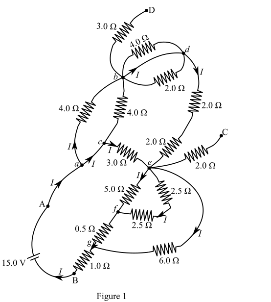
There are seven nodes a, b, c, d, e, f, and g as shown in Figure 1.
The nodes a and c are shorted, and thus there is no resistance between a and c.
Calculate the equivalent resistance between nodes a and b.
The
Recall the expression for equivalent resistance in a parallel connection.
Here,
Substitute
The equivalent resistance between nodes b and d is zero because nodes b and d are shorted. The
The equivalent resistance between nodes b and d is not in the circuit, because terminal d is open-circuited.
The
Calculate the equivalent resistance between nodes d and e.
Recall the expression for the equivalent resistance in a series connection.
Here,
Substitute
The equivalent resistance between nodes e and c is not in the circuit, because terminal c is open-circuited.
The
Calculate
Recall the expression for the equivalent resistance in a series connection.
Here,
Substitute
Now the
Calculate the equivalent resistance between nodes e and f.
Recall the expression for equivalent resistance in a parallel connection.
Here,
Substitute
Now the
Calculate
Recall the expression for the equivalent resistance in a series connection.
Here,
Substitute
Substitute
Now the
Calculate the equivalent resistance between nodes e and g.
Recall the expression for equivalent resistance in a parallel connection.
Here,
Substitute
Figure 2 shows the reduced form of Figure 1.
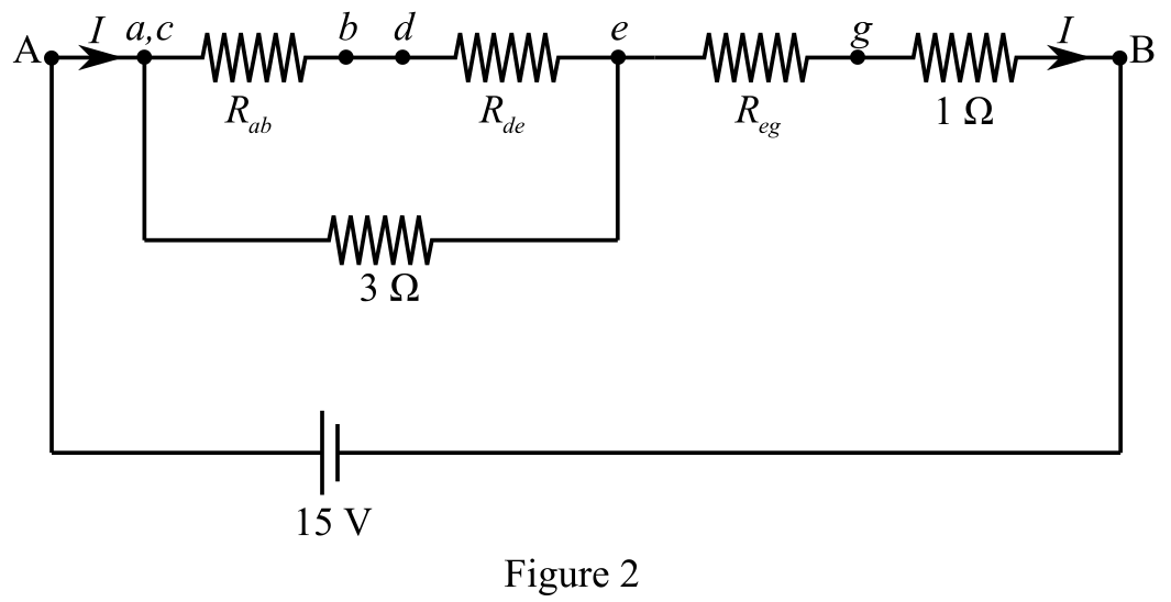
Calculate the equivalent resistance between nodes a and e.
Nodes b and d are shorted.
The resistor
Calculate
Recall the expression for the equivalent resistance in a series connection.
Here,
Substitute
Again substitute
Now, the
Calculate the equivalent resistance between nodes a and e.
Recall the expression for equivalent resistance in a parallel connection.
Here,
Substitute
Figure 3 shows the reduced form of Figure 2.
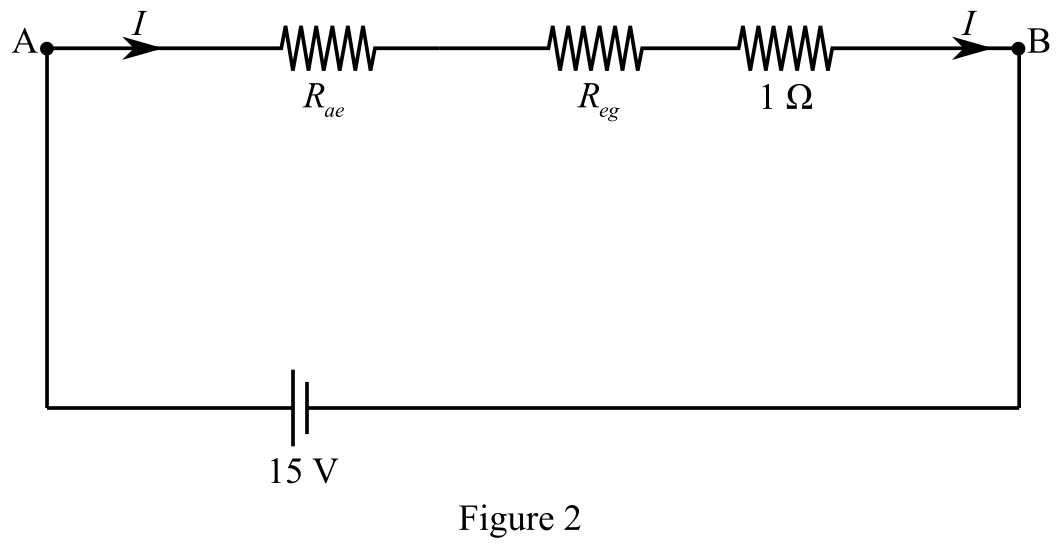
Calculate the equivalent resistance between terminals A and B.
The resistances
Recall the expression for the equivalent resistance in a series connection.
Here,
Substitute
Substitute
Conclusion:
Therefore, the equivalent resistance between terminals A and B is
(b)
The amount of the current flow from the
Answer to Problem 39SP
Solution:
Explanation of Solution
Given data:
Refer to Figure 3.
The power supply between terminals A and B is
The equivalent resistance between terminals A and B is
Formula used:
Write the expression for current from Ohm’s law.
Here,
Explanation:
Calculate the amount of the current flow through the
The current flow through the
Recall the expression for current from Ohm’s law.
Here,
Substitute
Conclusion:
Therefore, the current flow through the
(c)
The net power dissipated by all resistors in the circuit given in Fig. 28-22.
Answer to Problem 39SP
Solution:
Explanation of Solution
Given data:
The power supply between terminals A and B is
The total current flow between terminals A and B is
Formula used:
Write the expression for power.
Here,
The net power dissipated by all resistors in the given circuit is equal to the total power delivered by the power supply because the power supply does not have any internal resistance.
Explanation:
Calculate the total power delivered by the power supply.
Recall the expression for power.
Here,
Substitute
The total power delivered is equal to the power dissipated by all the resistors.
Conclusion:
Therefore, the power dissipated by all resistors in the given circuit is
Want to see more full solutions like this?
Chapter 28 Solutions
Schaum's Outline of College Physics, Twelfth Edition (Schaum's Outlines)


- When working with high-power electric circuits, it is advised that whenever possible, you work "one-handed” or “keep one hand in your pocket." Why is this a sensible suggestion?arrow_forwardDetermine the safe current and safe voltage of the following resistors: 200 Ω / 0.25W 20k Ω / 0.5W 4k Ω / 0.5W 720 Ω / 0.25W 822k Ω / 2Warrow_forwardYou connect a 10.0 MΩ resistor in series with a 3.20 mFcapacitor and a battery with emf 9.00 V. Before you close the switchat t = 0 to complete the circuit, the capacitor is uncharged. Find the fraction of the initial current present at t = 18.0 sarrow_forward
- A loop circuit has a resistance of R1 and a current of 1.9 A. The current is reduced to1.6 A when an additional 4.8 Ω resistor isadded in series with R1.What is the value of R1? Assume the internal resistance of the source of emf is zero.Answer in units of Ω.arrow_forwardCalculate the resistance in an RL circuit in which L = 2.50 H and the current increases to 90.0% of its final value in 3.00 s.arrow_forward
