
PHYSCS SCI&ENG/MOD PHYS V3&MOD MSTG
4th Edition
ISBN: 9780134614229
Author: Knight
Publisher: PEARSON
expand_more
expand_more
format_list_bulleted
Videos
Textbook Question
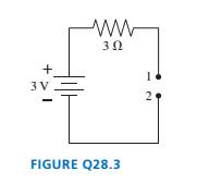
Chapter 28, Problem 3CQ
The wire is broken on the right side of the circuit in FIGURE Q28.3. What is the potential difference
Expert Solution & Answer
Want to see the full answer?
Check out a sample textbook solution
Students have asked these similar questions
Two resistors, R1 = 50 Ω and R2 = 17 Ω are connected in series to a battery providing voltage ΔVbat = 3.1 V. What is the potential difference measured across the resistor R2?
If the potential difference ∆V12 = -90 V, the potential difference ∆V23 = 0 V, and the potential difference ∆V41 = -60 V, what is the potential difference ∆V34?
5 part A:
If u(C) = 0.2C. What in the uncertainty of a 500 mF capacitor in mF?
5 Part B:
If C = 500 mF and R = 8000 W , and V = 5 V. What is the voltage across the resistor in an RC circuit if it started out fully charged and the time since we started charging 6 seconds ago?
Chapter 28 Solutions
PHYSCS SCI&ENG/MOD PHYS V3&MOD MSTG
Ch. 28 - Rank in order, from largest to smallest, the...Ch. 28 - The tip of a flashlight bulb is touching the top...Ch. 28 - The wire is broken on the right side of the...Ch. 28 - The circuit of FIGURE Q28.4 has two resistors,...Ch. 28 - The circuit of FIGURE Q28.5 has two resistors,...Ch. 28 - Rank in order, from largest to smallest, the...Ch. 28 - Are the two resistors in FIGURE Q28.7 in series or...Ch. 28 - A battery with internal resistance r is connected...Ch. 28 - Initially bulbs A and B in FIGURE Q28.9 are...Ch. 28 - Bulbs A. B, and C in FIGURE Q28.1O axe identical,...
Ch. 28 - Bulbs A and B in FIGURE Q28.11 are identical, and...Ch. 28 - Prob. 12CQCh. 28 - FIGURE Q28.13 shows the voltage as a function of...Ch. 28 - Prob. 1EAPCh. 28 - Draw a circuit diagram for the circuit of FIGURE...Ch. 28 - Prob. 3EAPCh. 28 - Prob. 4EAPCh. 28 - a. What are the magnitude and direction of the...Ch. 28 - What is the magnitude of the potential difference...Ch. 28 - Prob. 7EAPCh. 28 - Prob. 8EAPCh. 28 - A 60 W lightbulb and a 100 W lightbulb are placed...Ch. 28 - Prob. 10EAPCh. 28 - The five identical bulbs in FIGURE EX2B.11 are all...Ch. 28 - Prob. 12EAPCh. 28 - Prob. 13EAPCh. 28 - A typical American family uses kWh of electricity...Ch. 28 - A waterbed heater uses 450 W of power. It is on 25...Ch. 28 - Prob. 16EAPCh. 28 - Prob. 17EAPCh. 28 - Prob. 18EAPCh. 28 - 19. The voltage across the terminals of a V...Ch. 28 - Prob. 20EAPCh. 28 - Prob. 21EAPCh. 28 - 22. Two of the three resistors in FIGURE EX28.22...Ch. 28 - What is the value of resistor R in FIGURE EX28.23?Ch. 28 - Prob. 24EAPCh. 28 - What is the equivalent resistance between points a...Ch. 28 - What is the equivalent resistance between points a...Ch. 28 - Prob. 27EAPCh. 28 - Prob. 28EAPCh. 28 - Prob. 29EAPCh. 28 - Prob. 30EAPCh. 28 - Prob. 31EAPCh. 28 - Prob. 32EAPCh. 28 - Prob. 33EAPCh. 28 - What is the time constant for the discharge of the...Ch. 28 - A 10F capacitor initially charged to 20C is...Ch. 28 - Prob. 36EAPCh. 28 - Prob. 37EAPCh. 28 - A capacitor is discharged through a resistor. The...Ch. 28 - Prob. 39EAPCh. 28 - 40. A refrigerator has a 1000 W compressor, but...Ch. 28 - Prob. 41EAPCh. 28 - An electric eel develops a potential difference...Ch. 28 - You have a resistor, a resistor, a resistor, and a...Ch. 28 - A 2.0 -m-long, 1.0 -mm-diameter wire has a...Ch. 28 - What is the equivalent resistance between points a...Ch. 28 - What are the emf and internal resistance of the...Ch. 28 - A string of holiday lights can be wired in series,...Ch. 28 - The circuit shown in FIGURE P28.48 is inside a 15...Ch. 28 - Suppose you have resistors 2.5,3.5, and 4.5 and a...Ch. 28 - A lightbulb is in series with a resistor. The...Ch. 28 - Prob. 51EAPCh. 28 - Prob. 52EAPCh. 28 - Prob. 53EAPCh. 28 - Prob. 54EAPCh. 28 - What are the battery current Ibatand the potential...Ch. 28 - A battery is a voltage source, always providing...Ch. 28 - A circuit you’re building needs an ammeter that...Ch. 28 - For the circuit shown in FIGURE P28.58, find the...Ch. 28 - For the circuit shown in FIGURE P28.59, find the...Ch. 28 - For the circuit shown in FIGURE P28.60, find the...Ch. 28 - What is the current through the 20 resistor in...Ch. 28 - For the circuit shown in FIGURE P28.62, find the...Ch. 28 - What is the current through the 10 resistor in...Ch. 28 - For what emf does the 200 resistor in FIGURE...Ch. 28 - Prob. 65EAPCh. 28 - Prob. 66EAPCh. 28 - Prob. 67EAPCh. 28 - II A circuit you're using discharges a 20F...Ch. 28 - A 150F defibrillator capacitor is charged to 1500V...Ch. 28 - Prob. 70EAPCh. 28 - A 0.25F capacitor is charged to 50 V. It is then...Ch. 28 - Prob. 72EAPCh. 28 - Prob. 73EAPCh. 28 - The capacitors in FIGURE P28.74 are charged and...Ch. 28 - Prob. 75EAPCh. 28 - Prob. 76EAPCh. 28 - Prob. 77EAPCh. 28 - Prob. 78EAPCh. 28 - Prob. 79EAPCh. 28 - Prob. 80EAPCh. 28 - Prob. 81EAPCh. 28 - Prob. 82EAP
Knowledge Booster


Learn more about
Need a deep-dive on the concept behind this application? Look no further. Learn more about this topic, physics and related others by exploring similar questions and additional content below.Similar questions
- (a) Determine the equilibrium charge on the capacitor in the circuit of Figure P27.46 as a function of R. (b) Evaluate the charge when R = 10.0 . (c) Can the charge on the capacitor be zero? If so, for what value of R? (d) What is the maximum possible magnitude of the charge on the capacitor? For what value of R is it achieved? (c) Is it experimentally meaningful to take R = ? Explain your answer. If so, what charge magnitude does it imply? Figure P27.46arrow_forwardIn the circuit of Figure P27.20, the current I1 = 3.00 A and the values of for the ideal battery and R are unknown. What are the currents (a) I2 and (b) I3? (c) Can you find the values of and R? If so, find their values. If not, explain. Figure P27.20arrow_forwardFour resistors are connected to a battery as shown in Figure P27.15. (a) Determine the potential difference across each resistor in terms of . (b) Determine the current in each resistor in terms of I. (c) What If? If R3 is increased, explain what happens to the current in each of the resistors. (d) In the limit that R3 , what are the new values of the current in each resistor in terms of I, the original current in the battery? Figure P27.15arrow_forward
- A Pairs of parallel wires or coaxial cables are two conductors separated by an insulator, so they have a capacitance. For a given cable, the capacitance is independent of the length if the cable is very long. A typical circuit model of a cable is shown in Figure P27.87. It is called a lumped-parameter model and represents how a unit length of the cable behaves. Find the equivalent capacitance of a. one unit length (Fig. P27.87A), b. two unit lengths (Fig. P27.87B), and c. an infinite number of unit lengths (Fig. P27.87C). Hint: For the infinite number of units, adding one more unit at the beginning does not change the equivalent capacitance.arrow_forwardThe resistance between terminals a and b in Figure P27.36 is 75.0 . If the resistors labeled R have the same value, determine R. Figure P27.36arrow_forwardThe circuit in Figure P21.59 has been connected for a long time. (a) What is the potential difference across the capacitor? (b) If the battery is disconnected from the circuit, over what time interval does the capacitor discharge to one-tenth its initial voltage?arrow_forward
- The- pair of capacitors in Figure P28.63 are fully charged by a 12.0-V battery. The battery is disconnected, and the switch is then closed. Alter 1.00 ms has elapsed, (a) how much charge remains 011 the 3.00-F capacitor? (b) How much charge remains on the 2.00-F capacitor? (c) What is the current in the resistor at this time?arrow_forwardThe speed of propagation of the action potential (an electric signal) in a nerve cell depends (inversely) on the diameter of the axon(nerve fiber). If the nerve cell connecting the spinal cord to your feet is 0.9 m long and the nerve impulse is 16 m/s. How long (in s) does it take for the nerve signal to travel this distance ?arrow_forwardA fully charged capacitor has a voltage of 100V and is then discharged through a resistor . The potential difference across the capacitor is 1V after 10 seconds. a) what is the time constant of the circuit? b) what is the potential difference across the capacitor at t=17seconds?arrow_forward
- A capacitor of capacitance C = 7.5 μF is initially uncharged. It is connected in series with a switch of negligible resistance, a resistor of resistance R = 11.5 kΩ, and a battery which provides a potential difference of VB = 110 V. (a) Calculate the time constant τ for the circuit in seconds. (b) After a very long time after the switch has been closed, what is the voltage drop VC across the capacitor in terms of VB? (c) Calculate the charge Q on the capacitor a very long time after the switch has been closed in C.arrow_forwardA circuit in the drawing shows two resistors, a capacitor, and a battery. When the capacitor is fully charged, what is the magnitude q of the charge on one of its plates?arrow_forwardA portion of a larger circuit is shown in the diagram below. The potential drop between points b and a is Vba = 4.0 V. Similarly, Vcb =3.5 V, Vcd = 2.0 V, Vdf = -0.5 V. Here, if Vba is greater than zero, then a is at a higher potential than b. Answer the following questions in SI units. 1. What is the potential difference Vgf? 2. What is the potential difference Vca? 3. What is the potential difference Vag?arrow_forward
arrow_back_ios
SEE MORE QUESTIONS
arrow_forward_ios
Recommended textbooks for you
 Physics for Scientists and Engineers with Modern ...PhysicsISBN:9781337553292Author:Raymond A. Serway, John W. JewettPublisher:Cengage Learning
 Physics for Scientists and EngineersPhysicsISBN:9781337553278Author:Raymond A. Serway, John W. JewettPublisher:Cengage Learning
 Principles of Physics: A Calculus-Based TextPhysicsISBN:9781133104261Author:Raymond A. Serway, John W. JewettPublisher:Cengage Learning
 Physics for Scientists and Engineers: Foundations...PhysicsISBN:9781133939146Author:Katz, Debora M.Publisher:Cengage Learning
 Physics for Scientists and Engineers, Technology ...PhysicsISBN:9781305116399Author:Raymond A. Serway, John W. JewettPublisher:Cengage Learning
Physics for Scientists and Engineers with Modern ...
Physics
ISBN:9781337553292
Author:Raymond A. Serway, John W. Jewett
Publisher:Cengage Learning
Physics for Scientists and Engineers
Physics
ISBN:9781337553278
Author:Raymond A. Serway, John W. Jewett
Publisher:Cengage Learning
Principles of Physics: A Calculus-Based Text
Physics
ISBN:9781133104261
Author:Raymond A. Serway, John W. Jewett
Publisher:Cengage Learning
Physics for Scientists and Engineers: Foundations...
Physics
ISBN:9781133939146
Author:Katz, Debora M.
Publisher:Cengage Learning
Physics for Scientists and Engineers, Technology ...
Physics
ISBN:9781305116399
Author:Raymond A. Serway, John W. Jewett
Publisher:Cengage Learning
DC Series circuits explained - The basics working principle; Author: The Engineering Mindset;https://www.youtube.com/watch?v=VV6tZ3Aqfuc;License: Standard YouTube License, CC-BY