Videos
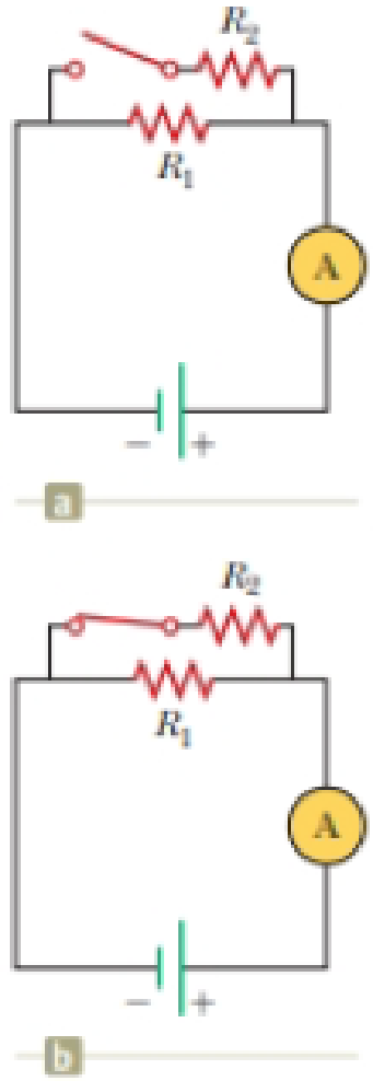
With the switch in the circuit of Figure 27.6a open, there is no current in R2. There is current in R1, however, and it is measured with the ammeter at the right side of the circuit. If the switch is closed (Fig. 27.6b), there is current in R2. What happens to the reading on the ammeter when the switch is closed? (a) The reading increases. (b) The reading decreases. (c) The reading does not change.
Figure 27.6 (Quick Quiz 27.3) What happens when the switch is closed?

Trending nowThis is a popular solution!

Chapter 28 Solutions
Physics for Scientists and Engineers with Modern, Revised Hybrid (with Enhanced WebAssign Printed Access Card for Physics, Multi-Term Courses)
Additional Science Textbook Solutions
University Physics Volume 1
College Physics: A Strategic Approach (3rd Edition)
Conceptual Integrated Science
University Physics with Modern Physics (14th Edition)
Schaum's Outline of College Physics, Twelfth Edition (Schaum's Outlines)
An Introduction to Thermal Physics


- In the circuit of Figure P27.25, the switch S has been open for a long time. It is then suddenly closed. Take = 10.0 V, R1 = 50.0 k, R2 = 100 k, and C = 10.0 F. Determine the time constant (a) before the switch is closed and (b) after the switch is closed. (c) Let the switch be closed at t = 0. Determine the current in the switch as a function of time. Figure P27.25 Problems 25 and 26.arrow_forwardIn the circuit of Figure P27.25, the switch S has been open for a long time. It is then suddenly closed. Determine the time constant (a) before the switch is closed and (b) after the switch is closed. (c) Let the switch be closed at t = 0. Determine the current in the switch as a function of time. Figure P27.25 Problems 25 and 26.arrow_forwardWith the switch in the circuit of Figure 21.18a open, there is no current in R2. There is current in R1, however, and it is measured with the ammeter at the right side of the circuit. If the switch is closed (Fig. 21.18b), there is current in R2. What happens to the reading on the ammeter when the switch is closed? (a) The reading increases. (b) The reading decreases. (c) The reading does not change.arrow_forward
- In the circuit shown in figure 1, epsilon is equal to 41.0 V, R1= 4 ohms, R2= 6 ohms, and R3= 3 ohms. (D) for the 3 ohm resistor calculate the current through the resistor with S open. (E) what is the potential difference Vabbetween points a and b when the switch S is closed? (F) for the 4 ohm resistor calculate the current through the resistor with S closed. (G) for the 6 ohm resistor calculate the current through the resistor with S closed (H) for the 3 ohm resistor calculate the current through the resistor with S closed. (I) for each resistor, does the current increase or decrease when S is closed?arrow_forwardA 1.00-MQ voltmeter is placed in parallel with a 75.0-kQ resistor in a circuit. If the current through the combination is kept the same as it was through the 75.0-kQ resistor alone, what is the percentage decrease in voltage?arrow_forwardThe current in a single-loop circuit with one resistance R is 6.6 A. When an additional resistance of 2.7 Ω is inserted in series with R, the current drops to 3.30 A. What is R?arrow_forward
- When the switch S of the circuit in the figure is opened, the potential difference between points A and B is 3.08 V. After the switch is closed, the potential difference between points A and B decreases to 2.97 V and the current through the circuit is 1.00 mA. Determine the value of the resistance R1 in Ohms.arrow_forwardA 12 volt car battery is being used to power a circuit with a total resistance of 0.5 Mega-ohm. a) What is the power (in watts) being used by this circuit? b) The circuit is switched on for exactly 27.3 days and then switched off. How much energy has the circuit used (in joules AND kilowatt-hours) in this time? c) If the current rate of hydro use is 10.1 cents per kilowatt-hour, how much would the use of this circuit contribute to your hydro bill (assuming that no other charges apply)?arrow_forwardThe capacitor in the circuit shown is fully charged by a 24 V battery. The switch is closed at t = 0. At sometime after the switch is closed, the voltage across the capacitor is measured to be 10 V. What is the current in the circuit at this time, in Ampere? C = 3.0 µF, and R = 2.0 02. Your answer needs to have 2 significant figures, including the negative sign in your answer if needed. Do not include the positive sign if the answer is positive. No unit is needed in your answer, it is already given in the question statement. Cilarrow_forward
- The circuit on the right contains three resistors, A, B, and C, which all have equal resistances. The emf is 110V. Which resistor dissipates the most thermal energy after the switch is closed? (Resistor A, B, or C). Why? What other quantity is maximized to tell you that the energy is maximized?arrow_forwardIn the figure shown, the total resistance is 15.0 kΩ and the fem of the battery is 24.0 V.the time constant is measured at 24.0 µs calculate a) the total capacitance of the circuit and b) the time it takes the voltage through the resistor to reach 16.0 V after the switch is closed.arrow_forwardin the circuit below, when the switch S is open, the current through R1is i1(open)= 1.636 A. When the switch is closed,this current changes to i1(closed)= 1.565 A. What are the emf and internal resistance of the battery?arrow_forward
 Principles of Physics: A Calculus-Based TextPhysicsISBN:9781133104261Author:Raymond A. Serway, John W. JewettPublisher:Cengage Learning
 Physics for Scientists and EngineersPhysicsISBN:9781337553278Author:Raymond A. Serway, John W. JewettPublisher:Cengage Learning
 Physics for Scientists and Engineers with Modern ...PhysicsISBN:9781337553292Author:Raymond A. Serway, John W. JewettPublisher:Cengage Learning
 Physics for Scientists and Engineers, Technology ...PhysicsISBN:9781305116399Author:Raymond A. Serway, John W. JewettPublisher:Cengage Learning