Concept explainers
Videos
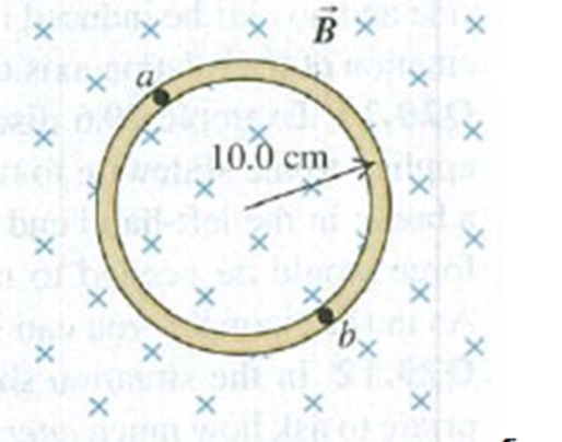
A circular loop of wire is in a region of spatially uniform magnetic field, as shown in Fig. E29.15. The magnetic field is directed into the plane of the figure. Determine the direction (clockwise or counterclockwise) of the induced current in the loop when (a) B is increasing; (b) B is decreasing; (c) B is constant with value B0. Explain your reasoning.
Figure E29.15

Learn your wayIncludes step-by-step video

Chapter 29 Solutions
University Physics with Modern Physics, Volume 1 (Chs. 1-20) and Mastering Physics with Pearson eText & ValuePack Access Card (14th Edition)
Additional Science Textbook Solutions
College Physics
Applied Physics (11th Edition)
The Cosmic Perspective
Sears And Zemansky's University Physics With Modern Physics
Lecture- Tutorials for Introductory Astronomy
Cosmic Perspective Fundamentals


- A constant magnetic field of 0.275 T points through a circular loop of wire with radius 3.50 cm as shown in Figure P32.1. a. What is the magnetic flux through the loop? b. Is a current induced in the loop? Explain. FIGURE P32.1arrow_forwardA piece of insulated wire is shaped into a figure eight as shown in Figure P23.12. For simplicity, model the two halves of the figure eight as circles. The radius of the upper circle is 5.00 cm and that of the lower circle is 9.00 cm. The wire has a uniform resistance per unit length of 3.00 Ω/m. A uniform magnetic field is applied perpendicular to the plane of the two circles, in the direction shown. The magnetic field is increasing at a constant rate of 2.00 T/s. Find (a) the magnitude and (b) the direction of the induced current in the wire. Figure P23.12arrow_forwardTwo frictionless conducting rails separated by l = 55.0 cm are connected through a 2.00- resistor, and the circuit is completed by a bar that is free to slide on the rails (Fig. P32.71). A uniform magnetic field of 5.00 T directed out of the page permeates the region, a. What is the magnitude of the force Fp that must be applied so that the bar moves with a constant speed of 1.25 m/s to the right? b. What is the rate at which energy is dissipated through the 2.00- resistor in the circuit?arrow_forward
- Figure P23.15 shows a top view of a bar that can slide on two frictionless rails. The resistor is R = 6.00 , and a 2.50-T magnetic field is directed perpendicularly downward, into the paper. Let = 1.20 m. (a) Calculate the applied force required to move the bar to the right at a constant speed of 2.00 m/s. (b) At what rate is energy delivered to the resistor? Figure P23.15 Problems 15 through 18.arrow_forwardReview. Figure P31.31 shows a bar of mass m = 0.200 kg that can slide without friction on a pair of rails separated by a distance = 1.20 m and located on an inclined plane that makes an angle = 25.0 with respect to the ground. The resistance of the resistor is R = 1.00 and a uniform magnetic field of magnitude B = 0.500 T is directed downward, perpendicular to the ground, over the entire region through which the bar moves. With what constant speed v does the bar slide along the rails?arrow_forwardA rectangular coil consists of N = 100 closely wrapped turns and has dimensions a = 0.400 m and b = 0.300 m. The coil is hinged along the y axis, and its plane makes an angle = 30.0 with the x axis (Fig. P22.25). (a) What is the magnitude of the torque exerted on the coil by a uniform magnetic field B = 0.800 T directed in the positive x direction when the current is I = 1.20 A in the direction shown? (b) What is the expected direction of rotation of the coil? Figure P22.25arrow_forward
- Review. Figure P31.31 shows a bar of mass m that can slide without friction on a pair of rails separated by a distance and located on an inclined plane that makes an angle with respect to the ground. The resistance of the resistor is R. and a uniform magnetic field of magnitude H is directed downward, perpendicular to the ground, over the entire region through which the bar moves. With what constant speed v does the bar slide along the rails?arrow_forwardThe bar in Figure OQ23.10 moves on rails to the right with a velocity v, and a uniform, constant magnetic field is directed out of the page. Which of the following statements are correct? More than one statement may be correct. (a) The induced current in the loop is zero. (b) The induced current in the loop is clockwise. (c) The induced current in the loop is counterclockwise. (d) An external force is required to keep the bar moving at constant speed. (e) No force is required to keep the bar moving at constant speed.arrow_forwardA rectangular conducting loop with dimensions w = 32.0 cm and h = 78.0 cm is placed a distance a = 5.00 cm from a long, straight wire carrying current I = 7.00 A in the downward direction (Fig. P32.75). a. What is the magnitude of the magnetic flux through the loop? b. If the current in the wire is increased linearly from 7.00 A to 15.0 A in 0.230 s, what is the magnitude of the induced emf in the loop? c. What is the direction of the current that is induced in the loop during this time interval?arrow_forward
- Consider the system pictured in Figure P28.26. A 15.0-cm horizontal wire of mass 15.0 g is placed between two thin, vertical conductors, and a uniform magnetic field acts perpendicular to the page. The wire is free to move vertically without friction on the two vertical conductors. When a 5.00-A current is directed as shown in the figure, the horizontal wire moves upward at constant velocity in the presence of gravity. (a) What forces act on the horizontal wire, and (b) under what condition is the wire able to move upward at constant velocity? (c) Find the magnitude and direction of the minimum magnetic Field required to move the wire at constant speed. (d) What happens if the magnetic field exceeds this minimum value? Figure P28.26arrow_forwardA rectangular toroid with inner radius R1= 7.0cm, outer radius R2= 9.0cm, height h = 3.0, and N=3.0, and N = 3000 turns is filled with an iron core a magnetic susceptibility 5.2 × 10³. (a) What is the self-inductance of the toroid? (b) If the current through the toroid is 2.0 A, what is the magnetic field at the center of the core? (c) For this same 2.0-A current, what is the effective surface current formed by the aligned atomic current loops in the iron core?arrow_forwardA loop of wire in the shape of a rectangle of width w and length L and a long, straight wire carrying a current I lie on a tabletop as shown in Figure P23.7. (a) Determine the magnetic flux through the loop due to the current I. (b) Suppose the current is changing with time according to I = a + bt, where a and b are constants. Determine the emf that is induced in the loop if b = 10.0 A/s, h = 1.00 cm, w = 10.0 cm, and L = 1.00 m. (c) What is the direction of the induced current in the rectangle? Figure P23.7arrow_forward
 Principles of Physics: A Calculus-Based TextPhysicsISBN:9781133104261Author:Raymond A. Serway, John W. JewettPublisher:Cengage Learning
 Physics for Scientists and Engineers with Modern ...PhysicsISBN:9781337553292Author:Raymond A. Serway, John W. JewettPublisher:Cengage Learning
 Physics for Scientists and Engineers: Foundations...PhysicsISBN:9781133939146Author:Katz, Debora M.Publisher:Cengage Learning
 Physics for Scientists and EngineersPhysicsISBN:9781337553278Author:Raymond A. Serway, John W. JewettPublisher:Cengage Learning
 Physics for Scientists and Engineers, Technology ...PhysicsISBN:9781305116399Author:Raymond A. Serway, John W. JewettPublisher:Cengage Learning