
Videos
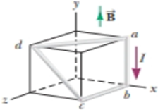
In Figure P28.28, the cube is 40.0 cm on each edge. Four straight segments of wire—ab, bc, cd, and da—form a closed loop that carries a current I = 5.00 A in the direction shown. A uniform magnetic field of magnitude B = 0.020 0 T is in the positive y direction. Determine the magnetic force vector on (a) ab, (b) bc, (c) cd, and (d) da. (c) Explain how you could find the force exerted on the fourth of these segments from the forces on the other three, without further calculation involving the magnetic field.
Figure P28.28
(a)
Answer to Problem 29.44P
Explanation of Solution
Given info: The length of each edge of the cube is
The formula for the magnetic force is,
Here,
As the current flows down and the magnetic from point
Substitute
The magnitude of the force is zero because an equal and opposite force cancels it due to which the magnetic force of
Conclusion:
Therefore, magnetic force vector on
(b)
Answer to Problem 29.44P
Explanation of Solution
Given info: The length of each edge of the cube is
The formula for the magnetic force is,
Here,
As the current flows down and the magnetic from point
Substitute
By using the Flemings right hand rule, the thumb points towards the x axis direction. Thus, the direction of the magnetic force is in
Conclusion:
Therefore, the magnetic force vector on
(c)
Answer to Problem 29.44P
Explanation of Solution
Given info: The length of each edge of the cube is
The formula for the magnetic force is,
Here,
Use Pythagoras theorem to find
Substitute
As the current flows at an angle and the magnetic from point b is perpendicular so the angle
Substitute
By using the Flemings right hand rule, the thumb points towards the z axis direction. Thus, the direction of the magnetic force is in z direction.
Conclusion:
Therefore, the magnetic force vector on
(d)
Answer to Problem 29.44P
Explanation of Solution
Given info: The length of each edge of the cube is
The formula for the magnetic force is,
Here,
Use Pythagoras theorem to find
Substitute
As the current flows vertically and the magnetic from point b is perpendicular so the angle
Substitute
By using the Flemings right hand rule, the thumb points towards the direction d
The direction of the force is,
Thus, the direction of the magnetic force is
Conclusion:
Therefore, the magnetic force vector on
(e)
Answer to Problem 29.44P
Explanation of Solution
Given info: The length of each edge of the cube is
By the parallelogram law of forces, when the forces on three of the arms of a parallelogram are provided then the magnitude of force on the forth arm is equal to the resultant of the other three forces.
According to the parallelogram law of vectors,
Here,
Conclusion:
Therefore, the force exerted on the forth segment from the forces on the other three can be calculated by the parallelogram law of vectors.
Want to see more full solutions like this?
Chapter 29 Solutions
EBK PHYSICS FOR SCIENTISTS AND ENGINEER


- A circular coil 15.0 cm in radius and composed of 145 tightly wound turns carries a current of 2.50 A in the counterclockwise direction, where the plane of the coil makes an angle of 15.0 with the y axis (Fig. P30.73). The coil is free to rotate about the z axis and is placed in a region with a uniform magnetic field given by B=1.35jT. a. What is the magnitude of the magnetic torque on the coil? b. In what direction will the coil rotate? FIGURE P30.73arrow_forwardTwo infinitely long current-carrying wires run parallel in the xy plane and are each a distance d = 11.0 cm from the y axis (Fig. P30.83). The current in both wires is I = 5.00 A in the negative y direction. a. Draw a sketch of the magnetic field pattern in the xz plane due to the two wires. What is the magnitude of the magnetic field due to the two wires b. at the origin and c. as a function of z along the z axis, at x = y = 0? FIGURE P30.83arrow_forwardIn Figure P22.43, the current in the long, straight wire is I1 = 5.00 A and the wire lies in the plane of the rectangular loop, which carries a current I2 = 10.0 A. The dimensions in the figure are c = 0.100 m, a = 0.150 m, and = 0.450 m. Find the magnitude and direction of the net force exerted on the loop by the magnetic field created by the wire. Figure P22.43 Problems 43 and 44.arrow_forward
- A wire carrying a current I is bent into the shape of an exponential spiral, r = e, from = 0 to = 2 as suggested in Figure P29.47. To complete a loop, the ends of the spiral are connected by a straight wire along the x axis. (a) The angle between a radial line and its tangent line at any point on a curve r = f() is related to the function by tan=rdr/d Use this fact to show that = /4. (b) Find the magnetic field at the origin. Figure P29.47arrow_forwardIn Figure P22.20, the cube is 40.0 cm on each edge. Four straight segments of wire—ab, bc, cd, and da—form a closed loop that carries a current I = 5.00 A in the direction shown. A uniform magnetic field of magnitude B = 0.020 0 T is in the positive y direction. Determine the magnetic force vector on (a) ab, (b) bc, (c) cd, and (d) da. (e) Explain how you could find the force exerted on the fourth of these segments from the forces on the other three, without further calculation involving the magnetic field.arrow_forwardTwo long, straight, parallel wires carry currents that are directed perpendicular to the page as shown in Figure P30.9. Wire 1 carries a current I1, into the page (in the negative z direction) and passes through the x axis at x = +. Wire 2 passes through the x axis at x = 2a and carries an unknown current I2. The total magnetic field at the origin due to the current-carrying wires has the magnitude 20I1(2a). The current I2 can have either of two possible values, (a) Find the value of with the smaller magnitude, stating it in terms of I1, and giving its direction. (b) Find the other possible value of I2.arrow_forward
- Figure P30.10 shows a circular current-carrying wire. Using the coordinate system indicated (with the z axis out of the page), state the direction of the magnetic field at points A and B.arrow_forwardWhy is the following situation impossible? Figure P28.46 shows an experimental technique for altering the direction of travel for a charged particle. A particle of charge q = 1.00 C and mass m = 2.00 1015 kg enters the bottom of the region of uniform magnetic field at speed = 2.00 105 m/s, with a velocity vector perpendicular to the field lines. The magnetic force on the particle causes its direction of travel to change so that it leaves the region of the magnetic field at the top traveling at an angle from its original direction. The magnetic field has magnitude B = 0.400 T and is directed out of the page. The length h of the magnetic field region is 0.110 m. An experimenter performs the technique and measures the angle at which the particles exit the top of the field. She finds that the angles of deviation are exactly as predicted. Figure P28.46arrow_forwardReview. In studies of the possibility of migrating birds using the Earths magnetic field for navigation, birds have been fitted with coils as caps and collars as shown in Figure P22.39. (a) If the identical coils have radii of 1.20 cm and are 2.20 cm apart, with 50 turns of wire apiece, what current should they both carry to produce a magnetic field of 4.50 105 T halfway between them? (b) If the resistance of each coil is 210 V, what voltage should the battery supplying each coil have? (c) What power is delivered to each coil? Figure P22.39arrow_forward
 Principles of Physics: A Calculus-Based TextPhysicsISBN:9781133104261Author:Raymond A. Serway, John W. JewettPublisher:Cengage Learning
 Physics for Scientists and Engineers: Foundations...PhysicsISBN:9781133939146Author:Katz, Debora M.Publisher:Cengage Learning
 Physics for Scientists and Engineers with Modern ...PhysicsISBN:9781337553292Author:Raymond A. Serway, John W. JewettPublisher:Cengage Learning
 Physics for Scientists and EngineersPhysicsISBN:9781337553278Author:Raymond A. Serway, John W. JewettPublisher:Cengage Learning
 Physics for Scientists and Engineers, Technology ...PhysicsISBN:9781305116399Author:Raymond A. Serway, John W. JewettPublisher:Cengage Learning