
Videos
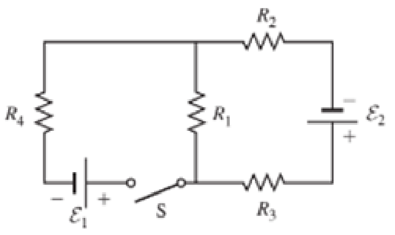
The emfs in Figure P29.43 are ε1 = 6.00 V and ε2 = 12.0 V. The resistances are R1 = 15.0 Ω, R2 = 30.0 Ω, R3 = 45.0 Ω, and R4 = 60.0 Ω. Find the current in each resistor when the switch is
- a. open and
- b. closed.
(a)
The current in each resistor when the switch is open.
Answer to Problem 43PQ
The current flowing through the resistor
Explanation of Solution
As the switch is kept open; the current in the wire EFAB will be zero as the circuit is disconnected.
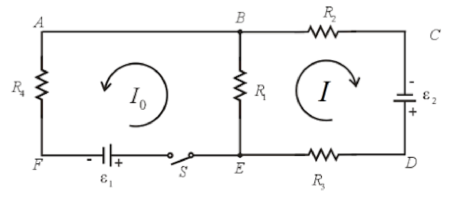
The resistors in the loop BCDEB are connected in series. The current flowing in all the elements in a series circuit is constant.
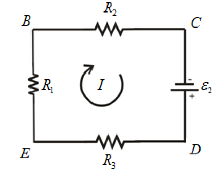
Write the expression for the equivalent resistance in the loop BCDEB as.
Here,
Write the expression for the current in the loop BCDEB as.
Here,
No current flows through the resistor
Conclusion:
Substitute
Substitute
Thus, the current flowing through the resistor
(b)
The current in each resistor when the switch is closed.
Answer to Problem 43PQ
The current flowing through the resistor
Explanation of Solution
The switch is closed, the current starts flowing through all the resistors in the circuit.
The circuit diagram for the closed switch is shown below.
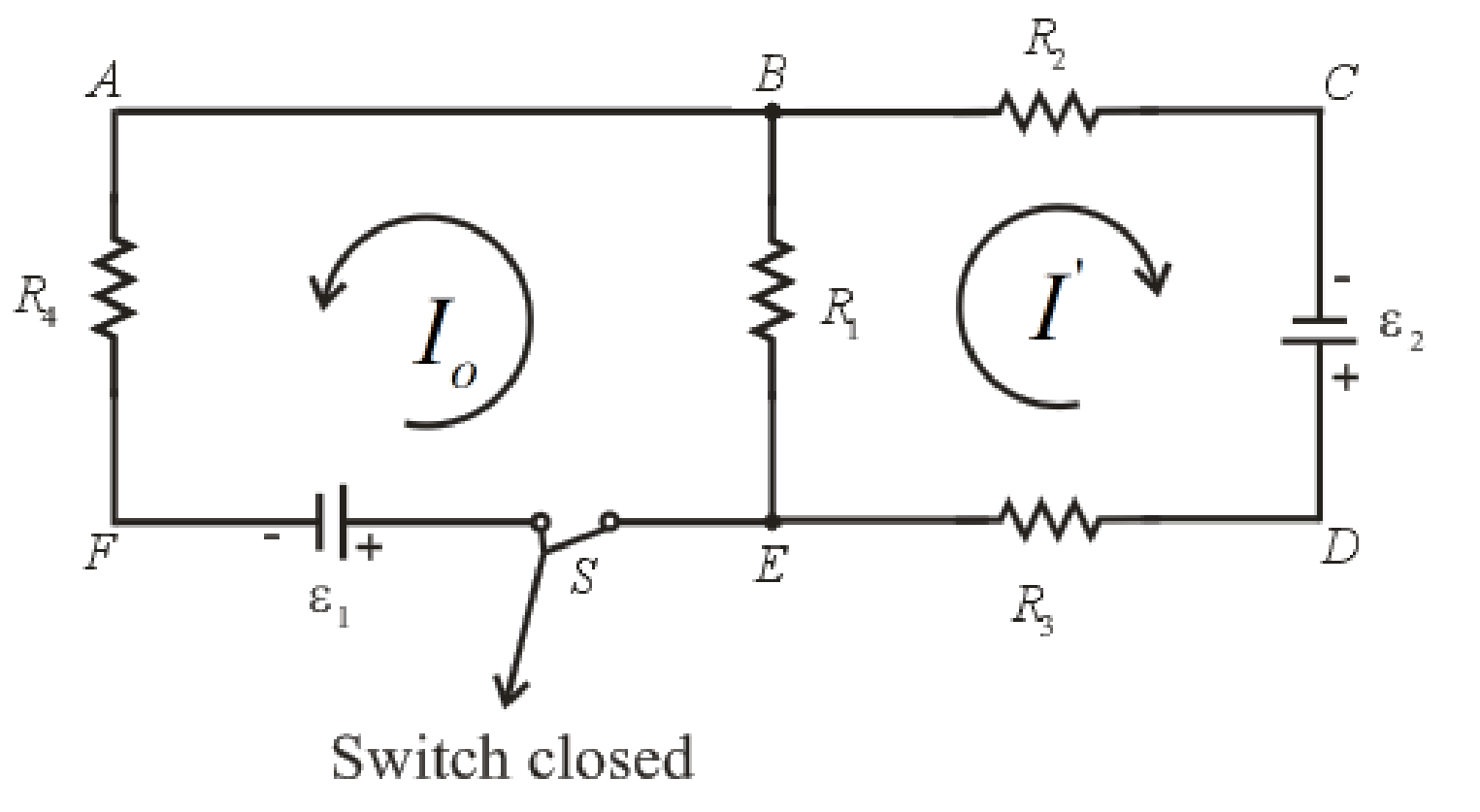
Write the expression for the Kirchhoff’s voltage law in loop ABCDEFA.
Here,
Write the expression for the Kirchhoff’s voltage law in loop ABEFA.
Write the expression for the current through resistor
Here,
Write the expression for the current through resistor
Here,
Write the expression for the current through resistor
Here,
Write the expression for the current through resistor
Here,
Conclusion:
Substitute
Rearrange the above equation for
Substitute
Substitute
Rearrange the above expression for
Substitute
Substitute
Substitute
Substitute
Substitute
Thus, the current flowing through the resistor
Want to see more full solutions like this?
Chapter 29 Solutions
Bundle: Physics For Scientists And Engineers: Foundations And Connections, Volume 1, Loose-leaf Version + Webassign Printed Access Card For Katz's ... And Connections, Single-term Courses


- Figure P29.84 shows a circuit that consists of two identical emf devices. If R1 = R2 = R and the switch is closed, find an expression (in terms of R and ) for the current I that is in the branch from point a to b.arrow_forwardFigure P29.60 shows a simple RC circuit with a 2.50-F capacitor, a 3.50-M resistor, a 9.00-V emf, and a switch. What are a. the charge on the capacitor, b. the current in the resistor, c. the rate at which the capacitor is storing energy, and d. the rate at which the battery is delivering energy exactly 7.50 s alter the switch is closed?arrow_forwardIn the circuit of Figure P27.25, the switch S has been open for a long time. It is then suddenly closed. Take = 10.0 V, R1 = 50.0 k, R2 = 100 k, and C = 10.0 F. Determine the time constant (a) before the switch is closed and (b) after the switch is closed. (c) Let the switch be closed at t = 0. Determine the current in the switch as a function of time. Figure P27.25 Problems 25 and 26.arrow_forward
- In the circuit of Figure P21.57, the switch S has been open for a long time. It is then suddenly closed. Take = 10.0 V, R1 = 50.0 k, R2 = 100 k, and C = 10.0 F. Determine the time constant (a) before the switch is closed and (b) after the switch is closed. (c) Let the switch be closed at t = 0. Determine the current in the switch as a function of time.arrow_forwardIn the circuit of Figure P27.25, the switch S has been open for a long time. It is then suddenly closed. Determine the time constant (a) before the switch is closed and (b) after the switch is closed. (c) Let the switch be closed at t = 0. Determine the current in the switch as a function of time. Figure P27.25 Problems 25 and 26.arrow_forwardIn the RC circuit shown in Figure P29.78, an ideal battery with emf and internal resistance r is connected to capacitor C. The switch S is initially open and the capacitor is uncharged. At t = 0, the switch is closed. a. Determine the charge q on the capacitor at time t. b. Find the current in the branch be at time t. What is the current as t goes to infinity?arrow_forward
- In Figure P29.81, N real batteries, each with an emf and internal resistance r, are connected in a closed ring. A resistor R can be connected across any two points of this ring, causing there to be n real batteries in one branch and N n resistors in the other branch. Find an expression for the current through the resistor R in this case.arrow_forwardA battery with = 6.00 V and no internal resistance supplies current to the circuit shown in Figure P27.9. When the double-throw switch S is open as shown in the figure, the current in the battery is 1.00 mA. When the switch is closed in position a, the current in the battery is 1.20 mA. When the switch is closed in position b, the current in the battery is 2.00 mA. Find the resistances (a) R1, (b) R2, and (c) R3. Figure P27.9 Problems 9 and 10.arrow_forwardFigure P29.77 shows a circuit with two batteries and three resistors. a. How much current flows through the 2.00- resistor? b. What is the potential difference between points a and b in the circuit?arrow_forward
- Two ideal emf devices are connected to a set of resistors as shown in Figure P29.47. Find an expression for the emf 2 in terms of 1, R1, R2, R3, R4, and the current through R4, labeled I1.arrow_forwardWhat is the equivalent resistance between points a and b of the six resistors shown in Figure P29.70? FIGURE P29.70arrow_forwardAn ideal emf device is connected to a set of resistors as shown in Figure P29.66. Find an expression for the current through the resistor R3 in terms of the emf and the resistances.arrow_forward
 Physics for Scientists and Engineers: Foundations...PhysicsISBN:9781133939146Author:Katz, Debora M.Publisher:Cengage Learning
 Principles of Physics: A Calculus-Based TextPhysicsISBN:9781133104261Author:Raymond A. Serway, John W. JewettPublisher:Cengage Learning
 Physics for Scientists and EngineersPhysicsISBN:9781337553278Author:Raymond A. Serway, John W. JewettPublisher:Cengage Learning
 Physics for Scientists and Engineers with Modern ...PhysicsISBN:9781337553292Author:Raymond A. Serway, John W. JewettPublisher:Cengage Learning
 Physics for Scientists and Engineers, Technology ...PhysicsISBN:9781305116399Author:Raymond A. Serway, John W. JewettPublisher:Cengage Learning