Videos
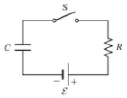
Figure P29.60 shows a simple RC circuit with a 2.50-μF capacitor, a 3.50-MΩ resistor, a 9.00-V emf, and a switch.
What are
- a. the charge on the capacitor,
- b. the current in the resistor,
- c. the rate at which the capacitor is storing energy, and
- d. the rate at which the battery is delivering energy exactly 7.50 s alter the switch is closed?
(a)
Find the charge on the capacitor.
Answer to Problem 60PQ
The charge on the capacitor at
Explanation of Solution
Write the expression for the initial charge on a capacitor as.
Here,
Write the expression for the charge in a series RC circuit as.
Substitute
Here,
Conclusion:
Substitute
Thus, the charge on the capacitor at
(b)
Find the current in the circuit.
Answer to Problem 60PQ
The current in the circuit at
Explanation of Solution
Write the expression for the initial current in the circuit as.
Here,
Write the expression for the current flowing in series RC circuit as.
Substitute
Here,
Conclusion:
Substitute
Thus, the current in the circuit at
(c)
Determine the rate at which the capacitor is storing energy.
Answer to Problem 60PQ
The rate of energy stored in the capacitor at
Explanation of Solution
Write the expression for the energy stored in a capacitor as.
Here,
Write the expression for the rate of storing energy in the capacitor as.
Substitute
Conclusion:
Substitute
Thus, the rate of energy stored in the capacitor at
(d)
The rate at which battery is delivering energy exactly
Answer to Problem 60PQ
The rate of energy delivered by battery at
Explanation of Solution
The rate of energy delivered by the battery is the power generated at the battery.
Write the expression for the rate of energy delivered by battery as.
Here,
Conclusion:
Substitute
Thus, the rate of energy delivered by battery at
Want to see more full solutions like this?
Chapter 29 Solutions
Student Solutions Manual For Katz's Physics For Scientists And Engineers: Foundations And Connections, Volume 1


- In the RC circuit shown in Figure P29.78, an ideal battery with emf and internal resistance r is connected to capacitor C. The switch S is initially open and the capacitor is uncharged. At t = 0, the switch is closed. a. Determine the charge q on the capacitor at time t. b. Find the current in the branch be at time t. What is the current as t goes to infinity?arrow_forwardThe circuit shown in Figure P28.78 is set up in the laboratory to measure an unknown capacitance C in series with a resistance R = 10.0 M powered by a battery whose emf is 6.19 V. The data given in the table are the measured voltages across the capacitor as a function of lime, where t = 0 represents the instant at which the switch is thrown to position b. (a) Construct a graph of In (/v) versus I and perform a linear least-squares fit to the data, (b) From the slope of your graph, obtain a value for the time constant of the circuit and a value for the capacitance. v(V) t(s) In (/v) 6.19 0 5.56 4.87 4.93 11.1 4.34 19.4 3.72 30.8 3.09 46.6 2.47 67.3 1.83 102.2arrow_forwardFigure P29.77 shows a circuit with two batteries and three resistors. a. How much current flows through the 2.00- resistor? b. What is the potential difference between points a and b in the circuit?arrow_forward
- An ideal emf device is connected to a set of resistors as shown in Figure P29.66. Find an expression for the current through the resistor R3 in terms of the emf and the resistances.arrow_forwardIn Figure P29.81, N real batteries, each with an emf and internal resistance r, are connected in a closed ring. A resistor R can be connected across any two points of this ring, causing there to be n real batteries in one branch and N n resistors in the other branch. Find an expression for the current through the resistor R in this case.arrow_forwardIn the circuit of Figure P27.25, the switch S has been open for a long time. It is then suddenly closed. Determine the time constant (a) before the switch is closed and (b) after the switch is closed. (c) Let the switch be closed at t = 0. Determine the current in the switch as a function of time. Figure P27.25 Problems 25 and 26.arrow_forward
- (a) What is the resistance of a lightbulb that uses an average power of 75.0 W when connected to a 60.0-Hz power source having a maximum voltage of 170 V? (b) What If? What is the resistance of a 100-W lightbulb?arrow_forwardIn the circuit of Figure P27.25, the switch S has been open for a long time. It is then suddenly closed. Take = 10.0 V, R1 = 50.0 k, R2 = 100 k, and C = 10.0 F. Determine the time constant (a) before the switch is closed and (b) after the switch is closed. (c) Let the switch be closed at t = 0. Determine the current in the switch as a function of time. Figure P27.25 Problems 25 and 26.arrow_forward
 Physics for Scientists and Engineers: Foundations...PhysicsISBN:9781133939146Author:Katz, Debora M.Publisher:Cengage Learning
 Physics for Scientists and Engineers with Modern ...PhysicsISBN:9781337553292Author:Raymond A. Serway, John W. JewettPublisher:Cengage Learning
 Principles of Physics: A Calculus-Based TextPhysicsISBN:9781133104261Author:Raymond A. Serway, John W. JewettPublisher:Cengage Learning
 Physics for Scientists and Engineers, Technology ...PhysicsISBN:9781305116399Author:Raymond A. Serway, John W. JewettPublisher:Cengage Learning
 Physics for Scientists and EngineersPhysicsISBN:9781337553278Author:Raymond A. Serway, John W. JewettPublisher:Cengage Learning